


Application of
Assembly
3 - 200
Embroidery unit
Application o
f
Assembly
Application of
Assembly
9
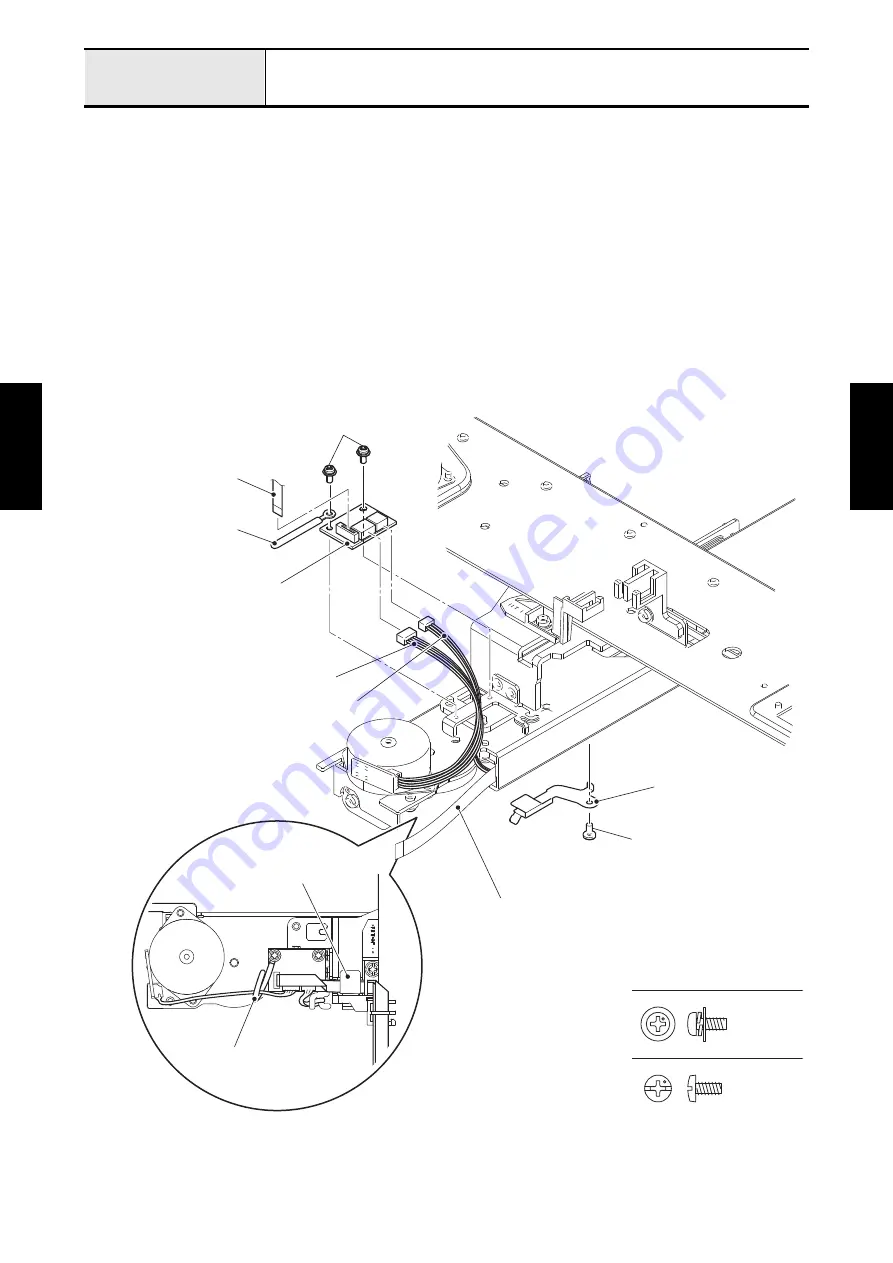
Attachment of Y relay PCB assy
1. Attach the Y relay PCB assy and clip to the X carriage unit with the two screws (screw, pan (S/P
washer) M3x7).
2. Connect the Y INIT PCB lead wire to the Y relay PCB assy. Connect the lead wire assy YPM to the Y
relay PCB assy, and clip the lead wire assy YPM together.
3. Connect the flexible flat cable:SML2CD-7 to the Y relay PCB assy, and lock it.
*Key point
• Refer to
"Wiring of Bending of Flexible flat cable:SML2CD-7"
"Wiring of X carriage unit (Y relay PCB
4. Pass the flexible flat cable:SML2CD-6 and flexible flat cable:SML2CD-7 through the securing fixtures,
set the code grip to them, and attach the code grip to the X carriage unit with the screw (screw, bind
M3x6).
*Key point
• Refer to
"Wiring of X carriage unit (Y relay PCB assy)"
.
Screw, Pan (S/P washer) M3X7
Screw, Bind M3X6
Screw, pan (S/P washer) M3x7
Y relay PCB assy
Lead wire assy YPM
Y INIT PCB lead wire
Code grip
Screw, bind M3x6
Flexible flat cable:SML2CD-6
Flexible flat cable:
SML2CD-7
Clip
Code grip
Clip
Summary of Contents for BLDY
Page 2: ......