


Application of
Assembly
3 - 189
Feed module
Application o
f
Assembly
Application of
Assembly
8
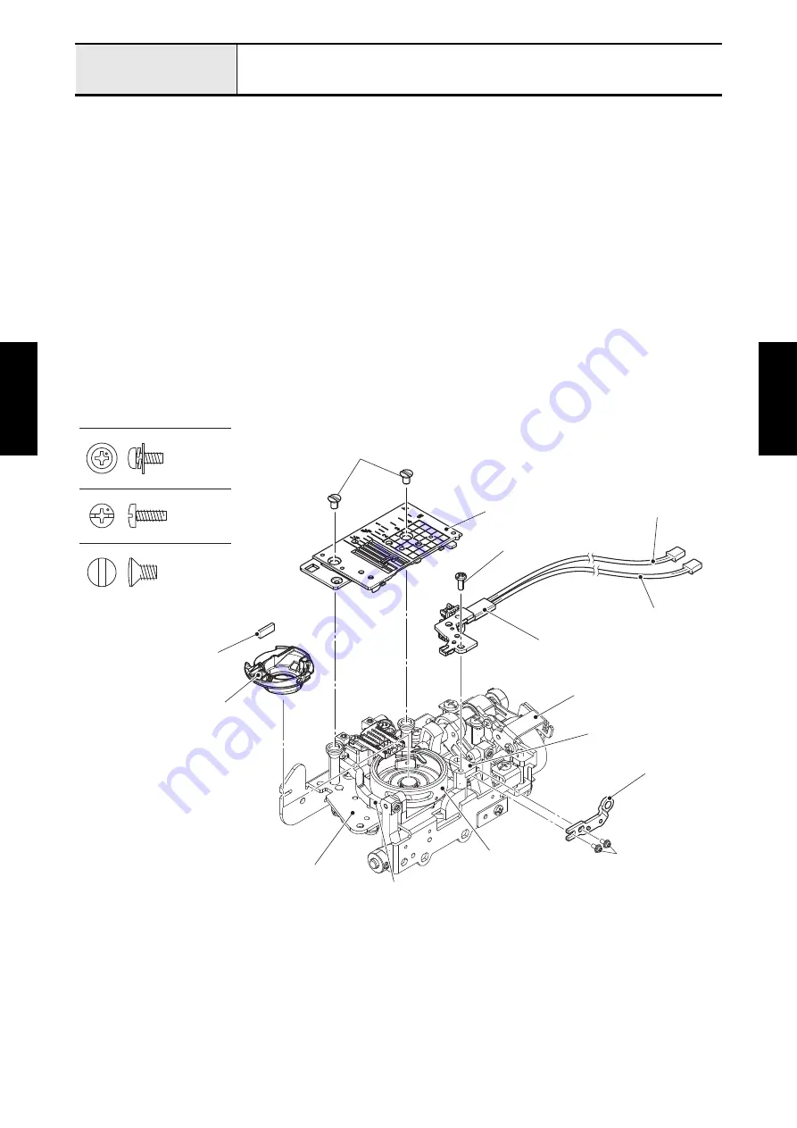
Attachment of Inner rotary hook bracket assy, Inner rotary hook assy and Needle plate A assy
1. Set the side feed adjust plate to the feed bar assy, and then tighten the two screws (screw, pan (S/P
washer) M3x7) temporarily.
*Key point
• Fully tighten the screw after performing
"Adjustment of Side feed straight stitch"
.
2. Align the boss of inner rotary hook bracket assy with the positioning hole of stopper plate block assy,
and set the inner rotary hook bracket assy to the stopper plate block assy, and then tighten the screw
(screw, bind M3x8) temporarily.
*Key point
• Fully tighten the screw after performing
"Adjustment of Inner rotary hook bracket position"
.
3. Attach the pile to the inner rotary hook assy, and set the inner rotary hook assy to the outer rotary hook
assy.
4. Attach the needle plate A assy to the base plate assy with the two screws (screw M4).
5. Bind up the PLTSW lead wire and the photo diode holder lead wire to the FPM sensor plate with the
band.
*Key point
• Refer to
.
Screw M4
Screw, Bind M3X8
Screw, Pan (S/P washer) M3X7
Needle plate A assy
Screw, bind M3x8
Inner rotary hook bracket assy
Side feed adjust plate
Inner rotary hook assy
Screw M4
Pile
Screw, pan
(S/P washer) M3x7
FPM sensor plate
Base plate assy
Outer rotary hook assy
PLTSW lead wire
Photo diode holder lead wire
Stopper plate block assy
Feed bar assy
Summary of Contents for BLDY
Page 2: ......