4. CONFIGURATION
You may set the
Check connection
flag in the second part of the window to enable au-
tomatic test messages for the cellular network. In some cases, the mobile WAN connection
could still be active but the router will not be able to send data over the cellular network. This
feature is used to verify that data can be sent over the PPP connection and supplements
the normal VRRP message handling. The currently active router (main/backup) will send test
messages to the defined
Ping IP Address
at periodic time intervals (
Ping Interval
) and wait for
a reply (
Ping Timeout
). If the router does not receive a response to the Ping command, it will
retry up to the number of times specified by the
Ping Probes
parameter. After that time, it will
switch itself to a backup router until the PPP connection is restored.
Item
Description
Ping IP Address
Destination IP address for the Ping commands. In VRRPv3 mode
you can use IPv4 or IPv6 address. You can not use a domain
name.
Ping Interval
Interval in seconds between the outgoing Pings.
Ping Timeout
Time in seconds to wait for a response to the Ping.
Ping Probes
Maximum number of failed ping requests.
Table 20: Check connection
You may use the DNS server of the mobile carrier as the destination IP address for the test
messages (Pings).
The
Enable traffic monitoring
option can be used to reduce the number of messages that
are sent to test the PPP connection. When this parameter is set, the router will monitor the
interface for any packets different from a ping. If a response to the packet is received within the
timeout specified by the
Ping Timeout
parameter, then the router knows that the connection is
still active. If the router does not receive a response within the timeout period, it will attempt to
test the mobile WAN connection using standard Ping commands.
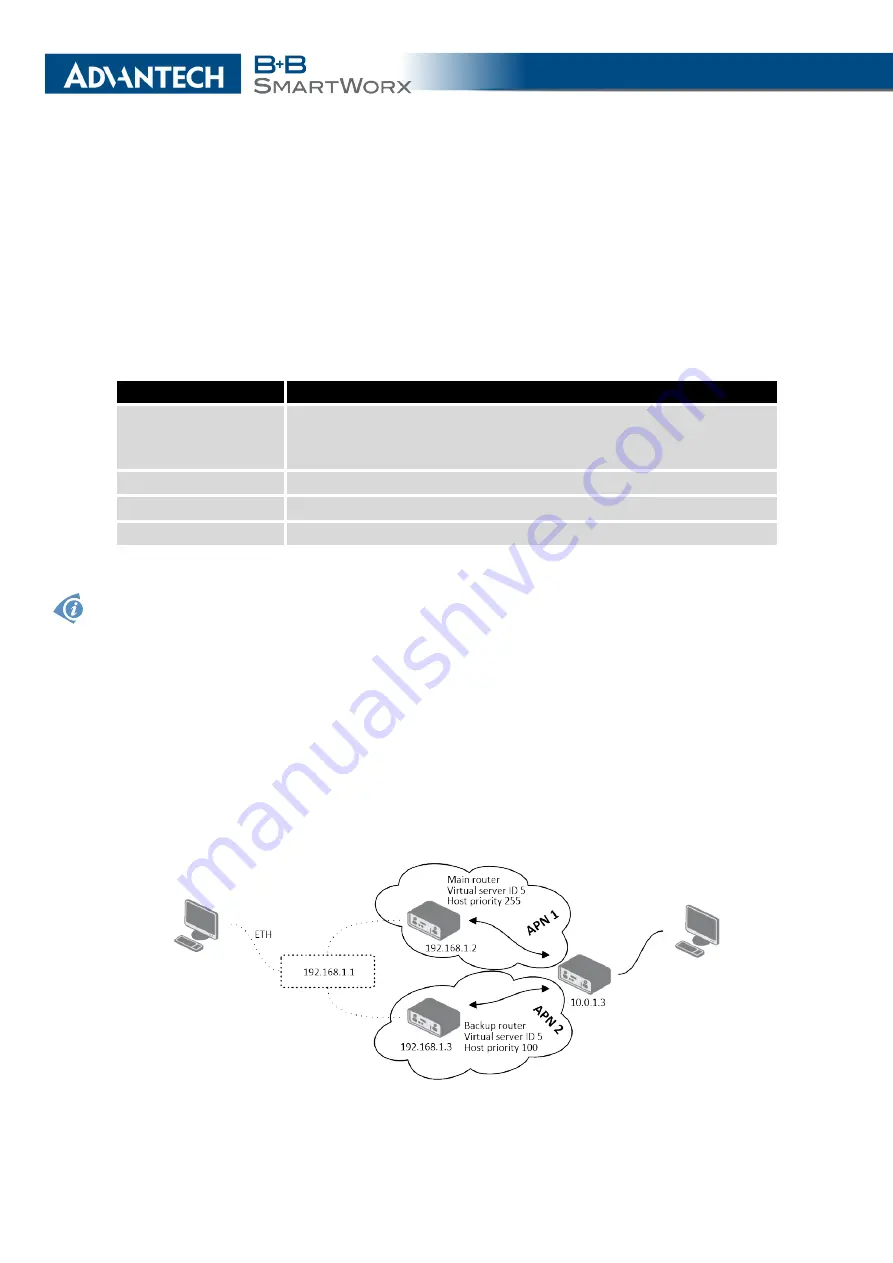
4.2.1
Example of VRRPv2 Configuration in IPv4 Network
Figure 20: Topology of VRRP Configuration example
31
Summary of Contents for SmartMotion
Page 1: ...Twin Cellular Module Router SmartMotion CONFIGURATION MANUAL ...
Page 24: ...3 STATUS WiFi Scan output may look like this Figure 4 WiFi Scan 14 ...
Page 27: ...3 STATUS Figure 5 Network Status 17 ...
Page 44: ...4 CONFIGURATION Figure 24 1st Mobile WAN Configuration 34 ...
Page 62: ...4 CONFIGURATION Figure 31 WiFi Configuration 52 ...
Page 86: ...4 CONFIGURATION Figure 46 IPsec Tunnels Configuration 76 ...
Page 112: ...4 CONFIGURATION Figure 67 Example 2 USB port configuration 102 ...


