your PC is set up for 1 start bit and 2 stop bits (The values are
fixed on the DMM).
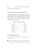
Check that the interface cable and adapters have been connectd
correctly, even the DB-9 Cable type, straight or crossover type.
Check that the interface cable has been connected to the correct
serial port on your PC (COM1, COM2, etc).
5.1 Pass/Fail Output
via
USB Connector
The USB connector, which comforns to USBTMC protocol, on the rear
panel of ATM3500A is a series “B” connector. When the USB interface is
disabled
(IEEE-488 interface is selected), the internal pass and fail
TTL output signals (limit testing) will be transmitted via the USB port.
The pass and fail signals are low true and indicate the Math Pass/Fail
Limit Test result for the
next
reading to be output to the GPIB
interface. The signals are active low for approximately 2ms (
±
100
µ
sec) for each reading taken.
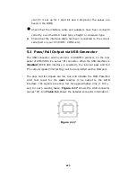
Figure 2-17
shows the USB connector
(series “B”). And
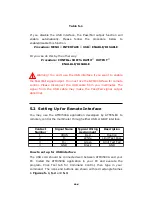
Table 5-1
shows the detailed connector information.
Figure 2-17
123

