Name
Range
Step Default
Description
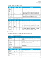
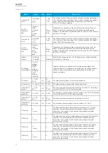
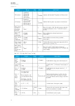
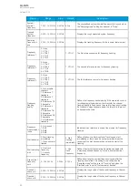
U3 mode U0
or SS
0: Not Used
1: U0
2: SS
-
0: Not
Used
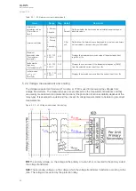
The voltage channel U3 can be used to measure zero sequence voltage
(U0) or the Synchrocheck voltage (SS). If neither is needed, the (default)
option "Not Used" should be active. This setting is only valid if the
"2LL+U3+U4" mode is selected.
U0 (U3)
Measured
from
0: Broken
Delta
1: Neutral
point
2: Open
delta
-
0:
Broken
delta
Defines how the secondary voltage is scaled to the primary. Does not
affect how protection operates, it only affects the displayed primary
voltages. This parameter is visible when the "U3 mode U0 or SS" has been
set to the "U0" mode.
U4 mode U0
or SS
0: Not Used
1: U0
2: SS
-
0: Not
Used
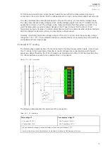
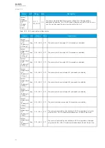
The voltage channel U4 can be used to measure zero sequence voltage
(U0) or the Synchrocheck voltage (SS). If neither is needed, the (default)
option "Not Used" should be active.
U0 (U4)
Measured
from
0: Broken
Delta
1: Neutral
point
2: Open
delta
-
0:
Broken
delta
Defines how the secondary voltage is scaled to the primary. Does not
affect how protection operates, it only affects the displayed primary
voltages. This parameter is visible when the "U4 mode U0 or SS" has been
set to the "U0" mode.
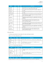
Voltage
memory
0: Disabled
1: Activated
-
0:
Disabled
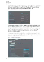
Activates the voltage memory. The "Voltage memory" chapter describes
the function in more detail.
P-E Voltage
measurements
0: No P-E
voltages
available
1: P-E
Voltages
calculated
2: P-E
Voltages
measured
-
-
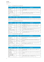
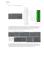
Indicates whether or not phase-to-earth voltages are available. Also
indicates whether P-E voltages are measured from the voltage channels
directly or if they are calculated from measured line-to-line and zero
sequence voltages.
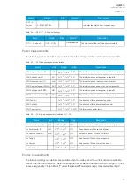
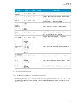
VT primary
1…1 000
000.0V
0.1V
20
000.0V
The rated primary voltage of the voltage transformer.
VT secondary
0.2…400.0V 0.1V
100.0V
The rated secondary voltage of the voltage transformer.
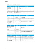
U3 Res/SS VT
primary
1…1 000
000V
0.1V
20
000.0V
The primary nominal voltage of the connected U0 or SS VT. This setting is
only valid if the "2LL+U3+U4" mode is selected.
U3 Res/SS VT
secondary
0.2…400V
0.1V
100.0V
The secondary nominal voltage of the connected U0 or SS VT. This setting
is only valid if the "2LL+U3+U4" mode is selected.
U4 Res/SS VT
primary
1…1 000
000V
0.1V
20
000.0V
The primary nominal voltage of the connected U0 or SS VT.
U4 Res/SS VT
secondary
0.2…400V
0.1V
100.0V
The secondary nominal voltage of the connected U0 or SS VT.
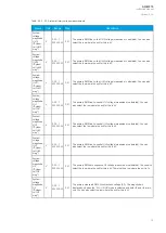
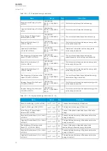
U1 Polarity
0: -
1: Invert
-
0: -
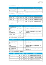
The selection of the first voltage measurement channel's (U1) polarity
(direction). The default setting is for the positive voltage to flow from
connector 1 to connector 2, with the secondary voltage's starpoint
pointing towards the line.
U2 Polarity
0: -
1: Invert
-
0: -
The selection of the second voltage measurement channel's (U2) polarity
(direction). The default setting is for the positive voltage to flow from
connector 1 to connector 2, with the secondary voltage's starpoint
pointing towards the line.
U3 Polarity
0: -
1: Invert
-
0: -
The selection of the third voltage measurement channel's (U3) polarity
(direction). The default setting is for the positive voltage to flow from
connector 1 to connector 2, with the secondary voltage's starpoint
pointing towards the line.
U4 Polarity
0: -
1: Invert
-
0: -
The selection of the fourth voltage measurement channel's (U4) polarity
(direction). The default setting is for the positive voltage to flow from
connector 1 to connector 2, with the secondary voltage's starpoint
pointing towards the line.
A
AQ
Q-M215
-M215
Instruction manual
Version: 2.04
71

