9.2.1.8 Low-impedance or high-impedance restricted earth fault/ cable end
differential protection (I0d>; 87N)
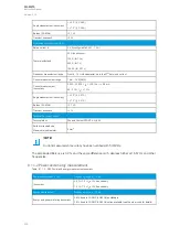
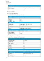
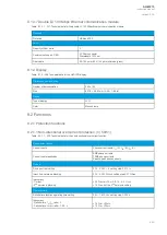
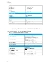
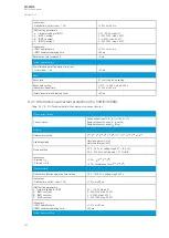
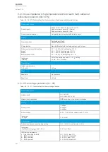
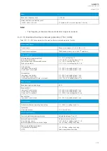
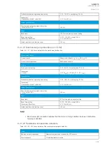
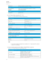
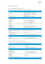
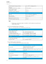
Table. 9.2.1.8 - 316. Technical data for the restricted earth fault/cable end differential function.
Measurement inputs
Current inputs
Phase current inputs: I
L1
(A), I
L2
(B), I
L3
(C)
Residual current channel I
01
(Coarse)
Residual current channel I
02
(Fine)
Current input calculations
Calculated bias and residual differential currents
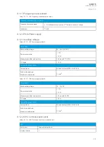
Pick-up
Operating modes
Restricted earth fault
Cable end differential
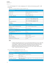
Characteristics
Biased differential with 3 settable sections and 2 slopes
Pick-up current sensitivity setting
Slope 1
Slope 2
Bias (Turnpoint 1 & 2)
0.01…50.00 % (I
N
), setting step 0.01 %
0.00…150.00 %, setting step 0.01 %
0.00…250.00 %, setting step 0.01 %
0.01…50.00 × I
N
, setting step 0.01 × I
N
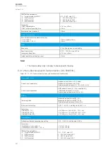
Inaccuracy
- Starting
±3% of the set pick-up value > 0.5 × I
N
setting.
±5 mA < 0.5 × I
N
setting
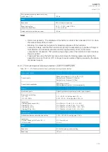
Operation time
Instant operation time
1.05 x I
SET
<30 ms
Reset
Reset ratio
No hysteresis
Reset time
<40 ms
9.2.1.9 Overvoltage protection (U>; 59)
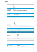
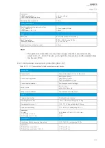
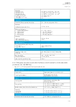
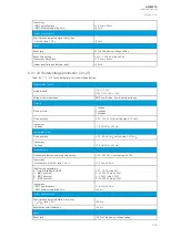
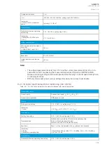
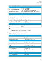
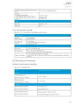
Table. 9.2.1.9 - 317. Technical data for the overvoltage function.
Measurement inputs
Voltage inputs
U
L1
, U
L2
, U
L3
U
L12
, U
L23
, U
L31
(+ U
0
)
Voltage input magnitudes
RMS line-to-line or line-to-neutral voltages
Pick-up
Pick-up terms
1 voltage
2 voltages
3 voltages
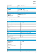
Pick-up setting
50.00…150.00 %U
N
, setting step 0.01 %U
N
Inaccuracy:
- Voltage
±1.5 %U
SET
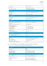
Operating time
Definite time function operating time setting
0.00…1800.00 s, setting step 0.005 s
Inaccuracy:
- Definite time (U
M
/U
SET
ratio 1.05
→
)
±1.0 % or ±35 ms
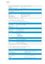
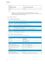
IDMT setting parameters:
k Time dial setting for IDMT
A IDMT constant
B IDMT constant
C IDMT constant
0.01…25.00, step 0.01
0…250.0000, step 0.0001
0…5.0000, step 0.0001
0…250.0000, step 0.0001
A
AQ
Q-M215
-M215
Instruction manual
Version: 2.04
447

