SwitchBlade x8106 Chassis Switch and AT-SBx81CFC960 Card Installation Guide
Section II: Installing the Chassis
141
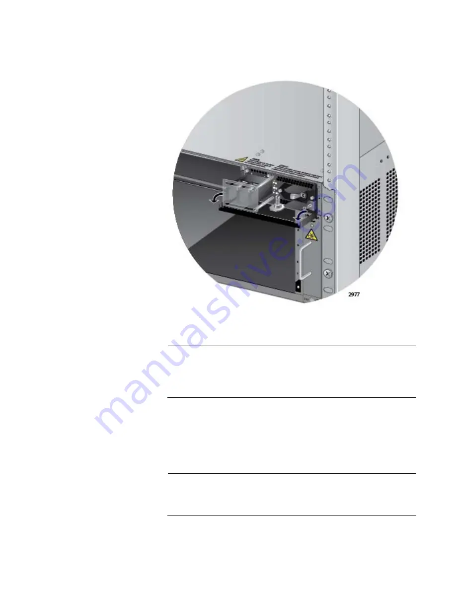
8. Lower the locking handle of the power supply module to secure the
module in the slot, as shown in Figure 68.
Figure 68. Locking the Handle on the AT-SBxPWRSYS1 DC System
Power Supply
Note
Do not tighten the handle locking screw yet. You may need to
slightly lift the handle to move the plastic guard panel when you
connect the positive and negative wires in “Powering On the AT-
SBxPWRSYS1 DC System Power Supply” on page 201.
9. To install a second AT-SBxPWRSYS1 DC System Power Supply,
repeat this procedure.
10. After installing the power supplies, go to Chapter 7, “Installing the AT-
SBx81CFC960 Controller and Ethernet Line Cards” on page 143.
Note
Retain the five wire ring lugs that come with the power supply. You
use them to wire the power supply in “Powering On the AT-
SBxPWRSYS1 DC System Power Supply” on page 201
Summary of Contents for AT-SB*81CFC960
Page 20: ...20...
Page 34: ...Chapter 1 Chassis and Power Supplies 34 Section I Hardware Overview...
Page 94: ...Chapter 3 AT SBx81CFC960 Controller Fabric Card 94 Section I Hardware Overview...
Page 96: ...96...
Page 142: ...Chapter 6 Installing the Power Supplies 142 Section II Installing the Chassis...
Page 230: ...Chapter 10 Powering On the Chassis 230 Section II Installing the Chassis...
Page 254: ...Chapter 12 Troubleshooting 254 Section II Installing the Chassis...
Page 298: ...Chapter 14 Upgrading the Controller Fabric Card 298 Section II Installing the Chassis...
Page 300: ...300...
Page 314: ...Chapter 15 VCStack Plus Overview 314 Section III Building a Stack with VCStack Plus...


