R01.43
22.10.2018
Page 111
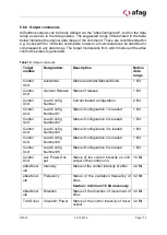
5.6.7 Input commands
All fieldbus inputs can be defined via "alexConfigurator". In the data range and also
data position. The suggested range of data listed in the table below gives the original
data range of the command, but all commands can be stretched or compressed to any
data range. The target module tells which module of the aflex control the command is
directed to. Thus, e.g. the aflex controlled via the target module "aflex module". The
control unit via the target module "control unit".
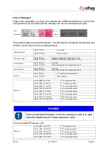
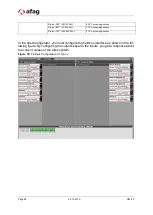
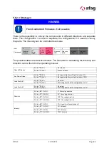
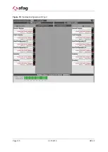
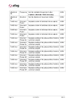
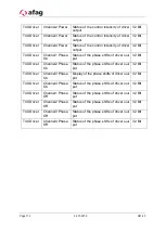
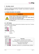
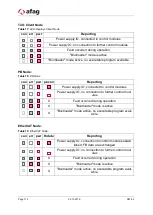
Table 14: Input commands
Target mod-
ule
Designa-
tion:
Description
Native
data
range
Control Unit: AutoMode: Possibility to switch between automatic/man-
ual mode. Manual mode: Parameters can only
be changed via the "aflexConfigurator". Auto-
matic mode: Parameters can only be changed
via the fieldbus interface. If the Configurator is
connected, the operating mode can not be
switched via the fieldbus.
1 Bit
Control Unit: General
Release
Release for the control of aflex. If the release
is not available, no power outputs are
switched.
1 Bit
Control Unit: Load Con-
fig Number
Load a saved configuration
8 Bit
Control Unit: Load Con-
fig Number
#1
Load a saved configuration (No. #1)
1 Bit
Control Unit: Load Con-
fig Number
#2
Load a saved configuration (No. #2)
1 Bit
Control Unit: Load Con-
fig Number
#3
Load a saved configuration (No. #3)
1 Bit
Control Unit: Load Con-
fig Number
#4
Load a saved configuration (No. #4)
1 Bit
Control Unit: Load Con-
fig Number
#5
Load a saved configuration (No. #5)
1 Bit
Control Unit: Aux Power
Output
Control of the 24V/4A PWM output on the con-
trol unit, e.g. for background lighting.
16 Bit
aflex-Mod-
ule
Intensity
Set the control intensity of aflex
32 Bit

