R01.43
22.10.2018
Page 95
5.6.2.1 Strategy 1
No conveying of components is given up. Components are merely isolated. In this
case, the "Direction" command is not required. For this, there is the possibility to call
up more different configurations and to control the intensity steps. If it is mandatory to
promote the development of components, Strategy 2 must be applied.
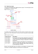
The digital inputs are defined as follows.
Input
0
1
2
3
4
5
6
7
Command
General
Release
Aux
Power
Output
Load
Config
#1
Load
Config
#2
Load
Config
#3
Intensity
LSB
Intensity
Intensity
MSB
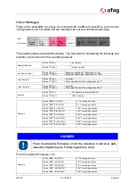
The possible states are described below. The formulas for calculating the intensity and
direction can be found in the operating manual.
General Release
Status
"0"
(0V):
No release
Status
"1"
(24V):
Present release
Aux Power Output
Status
"0"
(0V):
Background lighting off, light intensity = 0%
Status
"1"
(24V):
Background lighting on, light intensity = 100%
Load Config #1
Status
"0"
(0V):
No action
Status
"1"
(24V):
With rising flank load the configuration slot "1"
Load Config #2
Status
"0"
(0V):
No action
Status
"1"
(24V):
With rising flank load the configuration slot "2"
Load Config #3
Status
"0"
(0V):
No action
Status
"1"
(24V):
With rising flank load the configuration slot "3"
Intensity
Status
"000"
(0V,0V,0V):
0% Intensity = aflex switched off
Status
"100"
(0V,0V,0V):
14% Intensity
Status
"010"
(0V,24V,0V):
28% Intensity
Status
"110"
(24V,24V,0V):
42% Intensity
Status
"001"
(0V,0V,24V):
57% Intensity
Status
"101"
(24V,0V,24V):
71% Intensity
Status
"011"
(0V,24V,24V):
85% Intensity
Status
"111"
(24V,24V,24V):
100% Intensity
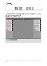
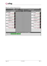
In the aflexConfigurator, you must configure the fieldbus interface as shown in the fol-
lowing figure. By defining the outputs equal to the inputs, you get a response about the
current values of the aflex system.

