R01.43
22.10.2018
Page 105
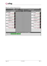
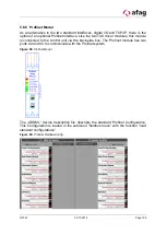
Figure 82: Profibus module FieldbusConfig
In order to establish a connection via the Profibus, an ID and a maximum available
data range are assigned to the Profibus module. In this example, ID 7 and a maximum
of 32 byte input/output data. These settings must match the settings of the Profibus
master.
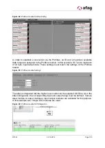
Figure 83: Profibus module Settings
The aflex is integrated into the higher-level control via the supplied .GSD file. As in the
aflexConfigurator, the corresponding input and output range must be defined. Various
input module or output module or input-output modules are available for this purpose.
In this example, two 16 byte DIO modules are used.
Figure 84: Profibus module SPS Integration

