LINE SECTIONALIZING USING A PLC AND ABB PROTECTIVE RELAY
Page 5 of 53
Compact PLC
ABB
40110
40100
MSTR
30
TPU 2000R relay
6XXX MEMORY CONSTANTS
READ TPU STATUS (REG. 40129)
TRANSFER TO PLC REG. 41700
PTR 1
READ TPU CURRENTS/ANGLES
(REG 40385) TRANSFER TO PLC
REG. 41701 [ 16 Registers ].
PTR 2
READ TPU VOLTAGE/ANGLES
(40513) TRANSFER TO PLC REG.
41717[6 Registers].
PTR 3
READ TPU POWER VALUES
(40528) TRANSFER TO PLC REG.
41727 [ 10 Registers ].
PTR 4
READ TPU ALARM STATUS
VALUES (41153) TRANSFER TO
PLC REG. 41723 [4 Registers].
PTR 5
1. TRANSFER 6XXXX MEMORY REGISTERS TO MSTR
CONFIGURATION BLOCK (40100 to 40106)
2. EXECUTE MASTER INSTRUCTION.
3. RETREIVE DATA READ FROM TPU AND PLACED IN
PLC REGISTER 40110. PLACE DATA IN BUFFER 417XX to STORE
4. INCREMENT POINTER FOR TPU READ INSTRUCTIONS 1 - 5.
PTR 1
PTR 2
PTR 3
PTR 4
PTR 5
TPU STATUS REG 41700
TPU CURRENTS/ANGLES
REGISTERS 41701 THRU
41716.
TPU VOLTAGES/ANGLES
REGISTERS 41717 THRU
41722.
TPU VOLTAGE VALUES
REGISTERS 41723 THRU
41726.
TPU ALARM STATUS
VALUES REGISTERS
41727 THRU 41736
WRITE TPU EXECUITE
INSTRUCTION (REG 41410)
WRITE TPU TRIP SETUP
INSTRUCTIONS (REGS
41411-41415)
WRITE TPU RESET TARGET
INSTRUCTIONS (REGS
41411 - 41415)
WRITE TPU RESET ALARM
INSTRUCTIONS (REGS
41411 - 41415)
WRITE TPU RESET STATUS
INSTRUCTIONS (REGS
41411 - 41415)
PTR 6 *
PTR 7
PTR 8
PTR 9
PTR 10
* Paired Instruction - Write index
one index (7 - 10) first then Ptr 6
last to execute instruction.
CYCLIC POLL INSTRUCTIONS
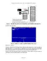
Figure 3. Data Map Request from the Compact PLC and TPU2000R via Modbus Plus
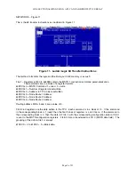
The MSTR block logic follows.
Figure 4. Network 1 Ladder Logic (MSTR Modbus Plus Logic)
NETWORK 1 – Figure 4:
The logic is written with cyclic polling occurring to gather the data and place it in a 4X memory space as
illustrated in Figure 3. If a command is to be initiated via the ladder logic program (AUTOMATIC
RESTORATION) or via the operator interface (MAGELIS), a specific request pointer is placed into a FIFO
buffer for immediate execution once the present command is executed by the MSTR block.
Network 1 senses that a pending command is to be executed in the FIFO block and the current command
is terminated in the cyclic polling sequence for the MSTR block.
Summary of Contents for REL 356
Page 23: ...ABB REL 356 Current Differential Protection 1 10 Product Overview and Specifications ...
Page 83: ...ABB REL 356 Current Differential Protection 3 36 Settings and Application ...
Page 127: ...ABB REL 356 Current Differential Protection 5 28 Testing ...
Page 186: ...LINE SECTIONALIZING USING A PLC AND ABB PROTECTIVE RELAY Page 49 of 53 ...
Page 187: ...LINE SECTIONALIZING USING A PLC AND ABB PROTECTIVE RELAY Page 50 of 53 ...
Page 188: ...LINE SECTIONALIZING USING A PLC AND ABB PROTECTIVE RELAY Page 51 of 53 ...
Page 189: ...LINE SECTIONALIZING USING A PLC AND ABB PROTECTIVE RELAY Page 52 of 53 ...

