MODEM COMMUNICATION TO ABB RELAYS
Page 5 of 47
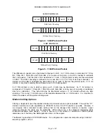
START 1 2 3 4 5 6 7 PARITY STOP
With Parity Checking
START 1 2 3 4 5 6 7 STOP STOP
Without Parity Checking
10 BIT PROTOCOL
Figure 4. 10 Bit Protocol Packet
With Parity Checking
Without Parity Checking
START 1 2 3 4 5 6 7 8 PARITY STOP
START 1 2 3 4 5 6 7 8 STOP STOP
11 BIT PROTOCOL
Figure 5. 11 Bit Protocol Packet
The difference in packet size is illustrated in Figures 4 and 5. An 10 bit protocol is comprised of 1 Stop
Bit, 1 Stop Bit, 1 Parity Bit, and 7 Data Bits or in the case of no parity, a stop bit is inserted to complete
the 10 bit packet. Thus the total of bits transferred is 10 bits. 10 bit protocols usually are those encoded
in ASCII. The ASCII encoding is defined to be a code from 00 to 7E (7 bits of data per character). A
modem must be able to anticipate the data packet size in order to transfer the protocol bytes. A 10 bit
modem is only able to reliably transmit/receive such 10 bit data packets.
An 11 Bit protocol is one in which a byte’s worth of data may be transferred. An 11 bit protocol is
comprised of 1 Stop Bit, 1 Parity Bit, 1 Start Bit, and 8 Data Bits or in the case of no parity an additional
stop bit is substituted. Thus byte data may be transferred using an 11 bit modem without any data
encoding. This is why 11 bit data may not be transferred/received via a 10 bit modem. It is important to
match the modem with the protocol being used.
Modem Cabling Options
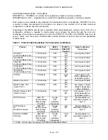
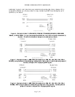
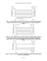
Cabling is dependent upon the devices attached and modem control options enabled. Through the “AT”
modem command set such capabilities as RTS/CTS control, CD, DTR enable is possible. However, if
one requires that a standard modem setting shall not be changed from location to location, signal
jumpering through the cable may be preferable. What follows are a few diagrams illustrating cable
connection between some devices. If one is unsure as to the function or emulation of RS232 please
reference one of the many fine ABB application notes on the subject.
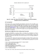
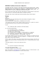
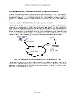
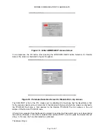
The Modem is generally a DCE RS232 device. It is configured via a personal computer using a terminal
emulator program such as:
Summary of Contents for REL 356
Page 23: ...ABB REL 356 Current Differential Protection 1 10 Product Overview and Specifications ...
Page 83: ...ABB REL 356 Current Differential Protection 3 36 Settings and Application ...
Page 127: ...ABB REL 356 Current Differential Protection 5 28 Testing ...
Page 186: ...LINE SECTIONALIZING USING A PLC AND ABB PROTECTIVE RELAY Page 49 of 53 ...
Page 187: ...LINE SECTIONALIZING USING A PLC AND ABB PROTECTIVE RELAY Page 50 of 53 ...
Page 188: ...LINE SECTIONALIZING USING A PLC AND ABB PROTECTIVE RELAY Page 51 of 53 ...
Page 189: ...LINE SECTIONALIZING USING A PLC AND ABB PROTECTIVE RELAY Page 52 of 53 ...

