MODEM COMMUNICATION TO ABB RELAYS
Page 40 of 47
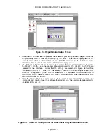
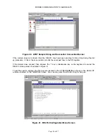
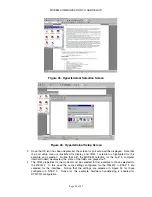
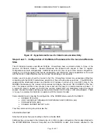
Figure 43. Hyperterminal Selection Screen
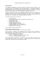
Figure 44. Hyperterminal Setup Screen
3.
Once the OK icon has been depressed, the screen for port setup will be displayed. Note that
the port setup menu is illustrated for display and COM 1 selection is highlighted for this
example and selection. Notice that with the MODEM selection (or the built in computer
internal modem) deselected, the some of the fields are “greyed out”.
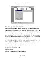
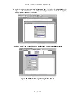
4.
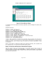
The COM properties for the modem must be selected for this example to those selected for
the REL512. In this case the same settings configured for the REL512 in STEP 3 are
selected for the interface. Notice that the settings are selected in Figure 45 for those
configured in STEP 3. Notice for this example, hardware handshaking is enabled for
RTS/CTS configuration.
Summary of Contents for REL 356
Page 23: ...ABB REL 356 Current Differential Protection 1 10 Product Overview and Specifications ...
Page 83: ...ABB REL 356 Current Differential Protection 3 36 Settings and Application ...
Page 127: ...ABB REL 356 Current Differential Protection 5 28 Testing ...
Page 186: ...LINE SECTIONALIZING USING A PLC AND ABB PROTECTIVE RELAY Page 49 of 53 ...
Page 187: ...LINE SECTIONALIZING USING A PLC AND ABB PROTECTIVE RELAY Page 50 of 53 ...
Page 188: ...LINE SECTIONALIZING USING A PLC AND ABB PROTECTIVE RELAY Page 51 of 53 ...
Page 189: ...LINE SECTIONALIZING USING A PLC AND ABB PROTECTIVE RELAY Page 52 of 53 ...

