MODEM COMMUNICATION TO ABB RELAYS
Page 31 of 47
Additional tips are covered in the following tips for LOCAL modem configuration (that modem attached to
the HYPERTERMINAL Personal Computer) and the REMOTE modem (that modem attached to the
REL512). Attach the cable from the PC to the modem undergoing the configuration process. It is
advisable to label each modem location since the LOCAL modem will be configured slightly differently
from the remote modem.
LOCAL MODEM
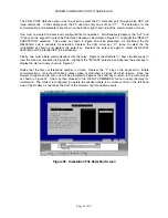
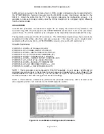
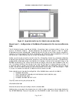
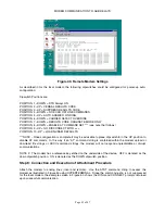
Local Modem parameters are illustrated in Figure 38. To display the current list of parameters, the
command string ATI4 should be typed in the HYPERTERMINAL environment. A list of the parameters
used is shown. The LOCAL modem may be configured via the dipswitches located underneath the relay.
The dipswitches correspond to the AT& commands. The US Robotics modem allows the modem to be
programmed via dipswitches (which are read upon power up). This allows the user to program select
parameters without connection to a HYPERTERMINAL screen and use of the AT command set.
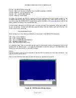
Dipswitch Positions are:
POSITION 1 –DOWN = DTR Always ON (&D0)
POSITION 2 –UP = VERBAL RESULTS CODE (V1)
POSITION 3 –DOWN = DISPLAY RESULTS CODE (Q1)
POSITION 4 –UP = ECHO OFFLINE COMMANDS (E1)
POSITION 5 –DOWN = SUPPRESS AUTO ANSWER
POSITION 6 –DOWN = CARRIER DETECT OVERRIDE (&C0)
POSITION 7 –UP = DISPLAY ALL RESULTS CODE
POSITION 8 –DOWN = ENABLE AT COMMAND SET
POSITION 9 –UP = NO DISCONNECT WITH +++ (O0)
POSITION 10 –DOWN = LOAD NVRAM DEFAULTS
NOTE 1: This local modem is only configured for DIAL OUT capability – no auto answer. Additionally, all
commands are echo’ed back to the terminal for easy access and troubleshooting. Upon Power UP the
NVRAM defaults are loaded into memory. It is also illustrates in Figure 34 that handshaking is enabled.
No other parameters have been changed from the default settings.
NOTE 2: The modem has a reference key etched on the underside of the device. OFF is denoted as the
down dipswitch position. ON is denoted as the DOWN dipswitch position.
Figure 38. Local Modem Configuration Parameters
Summary of Contents for REL 356
Page 23: ...ABB REL 356 Current Differential Protection 1 10 Product Overview and Specifications ...
Page 83: ...ABB REL 356 Current Differential Protection 3 36 Settings and Application ...
Page 127: ...ABB REL 356 Current Differential Protection 5 28 Testing ...
Page 186: ...LINE SECTIONALIZING USING A PLC AND ABB PROTECTIVE RELAY Page 49 of 53 ...
Page 187: ...LINE SECTIONALIZING USING A PLC AND ABB PROTECTIVE RELAY Page 50 of 53 ...
Page 188: ...LINE SECTIONALIZING USING A PLC AND ABB PROTECTIVE RELAY Page 51 of 53 ...
Page 189: ...LINE SECTIONALIZING USING A PLC AND ABB PROTECTIVE RELAY Page 52 of 53 ...

