LINE SECTIONALIZING USING A PLC AND ABB PROTECTIVE RELAY
Page 42 of 53
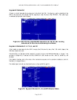
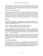
Segment 6 Network 4
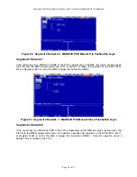
If there is no fault, calculate the loading prior to the trip of the TPU. This figure is used to determine if the
DPU at the other end of the feeder has the capability to drive the load of the PCD2000. The ladder logic
is illustrated in Figure 84 which follows.
Figure 84. If No TPU Trip Calculate KW Values Prior to Trip for Later Loading
Calculations for Bus Line Sectionalizing Calculations
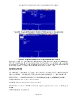
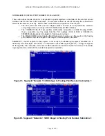
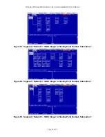
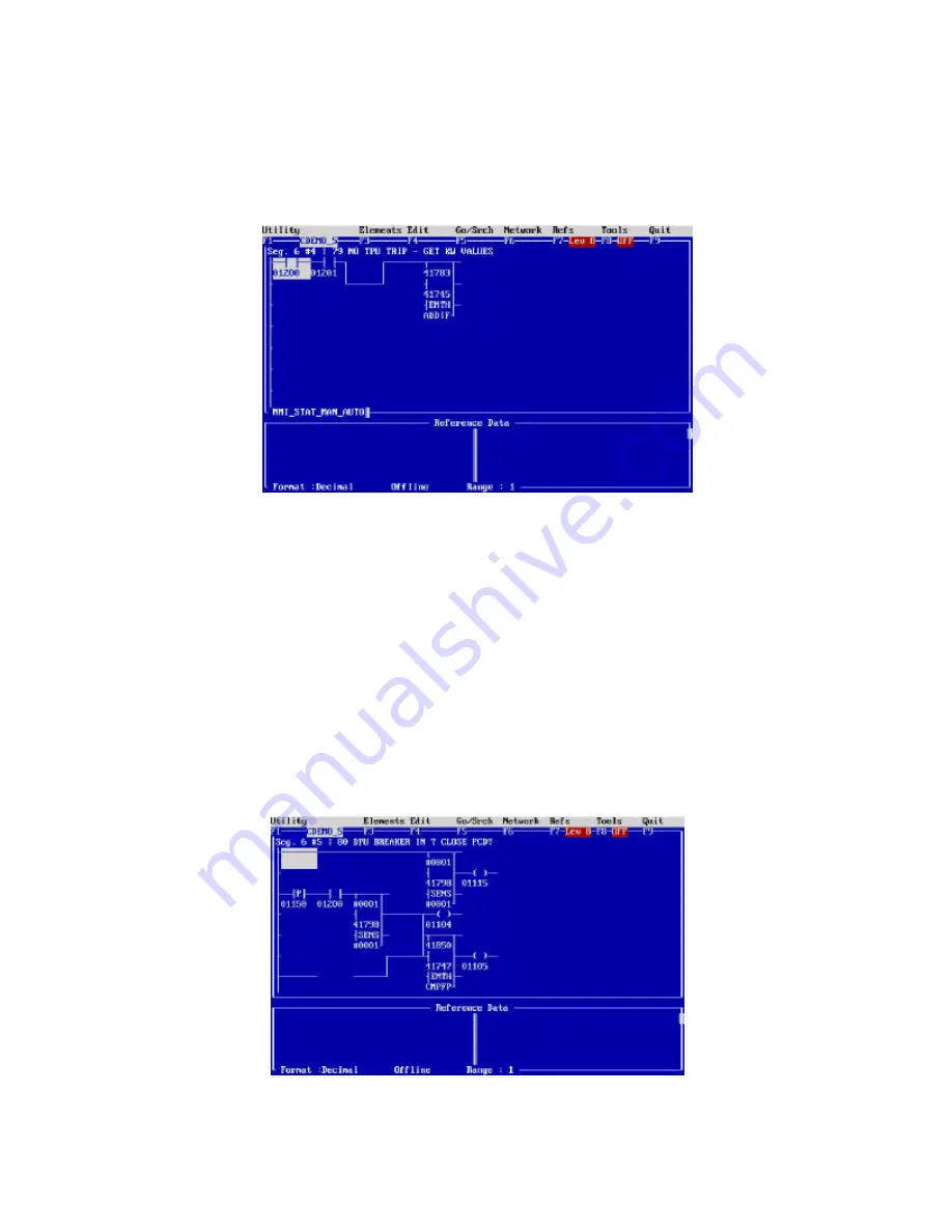
Segment 6 Networks 5, 6, 7, 8, 9, and 10
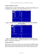
If the loading is appropriate for the DPU to supply the PCD circuit in lieu of the TPU which tripped, the
following sequence occurs.
The DPU status is checked and the breaker is closed as long as the TPU2000R breaker is tripped. The
program is delayed by 3 seconds and the PCD2000 is then closed and the close is verified by the
program.
The operator interface echo’s the state of the restoration sequence on the operator interface as each of
the steps is being performed.
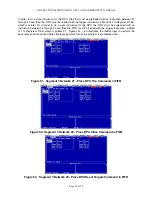
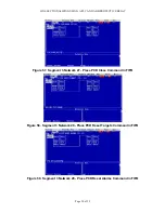
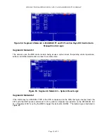
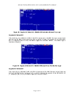
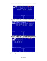
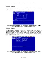
The ladder logic networks are illustrated below as Figures 85 through 90.
Figure 85. Segment 6 Network 5 – Check DPU Breaker Status
Summary of Contents for REL 356
Page 23: ...ABB REL 356 Current Differential Protection 1 10 Product Overview and Specifications ...
Page 83: ...ABB REL 356 Current Differential Protection 3 36 Settings and Application ...
Page 127: ...ABB REL 356 Current Differential Protection 5 28 Testing ...
Page 186: ...LINE SECTIONALIZING USING A PLC AND ABB PROTECTIVE RELAY Page 49 of 53 ...
Page 187: ...LINE SECTIONALIZING USING A PLC AND ABB PROTECTIVE RELAY Page 50 of 53 ...
Page 188: ...LINE SECTIONALIZING USING A PLC AND ABB PROTECTIVE RELAY Page 51 of 53 ...
Page 189: ...LINE SECTIONALIZING USING A PLC AND ABB PROTECTIVE RELAY Page 52 of 53 ...

