LINE SECTIONALIZING USING A PLC AND ABB PROTECTIVE RELAY
Page 19 of 53
6XXX File 1
6XXX File 2
600500
600510
600520
600530
600540
600550
600560
600570
600580
600590
600600
600610
600620
600630
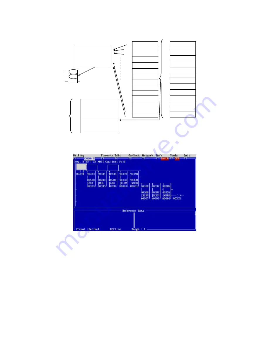
READ DPU STATUS
Parameterize the
XMIT Block
Regs 40308 to
40 315
Data to Parameterize
the Modbus Instructions
at 40355 to 40384 and
also to store write data
parameters for control
610500
610530
610590
610620
610650
610680
610710
610740
610770
610800
610830
610860
610890
610920
Read 1DPU Reg 40129 to PLC41750
Read 26 DPU Regs 40257 to PLC41751
Read 4 DPU Regs 40283 to PLC 41777
Read 2 DPU Regs 40898 to PLC 41793
Read 2 DPU Regs 40905 to PLC 1798
Read 1DPU Reg 40129 to PLC41750
Read 26 DPU Regs 40257 to PLC41751
Read 4 DPU Regs 40283 to PLC 41777
Read 2 DPU Regs 40898 to PLC 41793
Read 2 DPU Regs 40905 to PLC 1798
40300
XMIT
16
#0001
40308 = Coommand Word
40309 =Message Pointer (355)
40310 = Buffer Length (5 Fixed by Modbus)
40311 =Response Timeout (mS)
40312=Retry Limit
40313 =Start of TransmitDelay
40314 =End of Transmit Delay
40315 =Current Retry Count
CYCLIC
POLL
(40330
counter)
40309 = TRANSER COMMAND TO 40355
40310 = 5 Registers
40355 = Modbus Function Code
40356 = Quantity of Register Read/Written
40357 = DPU or PCD Address
40358 = DPU/PCD Data Address to Read or Write
40359 = 0X or 4X data address in PLC
to placeDPU /PCD data read
or address to obtain data to write to DPU/PCD
40360= Data Area to Store for WRITE instructions
40384=
Read 1DPU Reg 40129 to PLC41750
Read 26 DPU Regs 40257 to PLC41751
Read 4 DPU Regs 40283 to PLC 41777
Read 2 DPU Regs 40898 to PLC 41793
Read 2 DPU Regs 40905 to PLC 1798
Read 1PCD Reg 40129 to PLC41800
Read 26 PCD Regs 40257 to PLC41801
Read 4 PCD Regs 40283 to PLC 41827
Read 2 PCD Regs 40898 to PLC 41842
Read 2 PCD Regs 40905 to PLC 41847
PTR 1
PTR 2
PTR 3
PTR 4
PTR 5
PTR 6
PTR 7
PTR 8
PTR 9
PTR 10
PTR 11
PTR 12
PTR 13
PTR 14
COUNTER
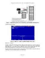
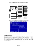
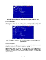
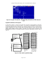
Figure 31. XMIT Parameterization Philosophy for Data Control
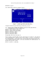
Figure 32. Segment 3 Network 3 – 6X Pointer Computation Logic for Loading XMIT
Instruction
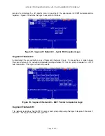
Segment 3 Network 4:
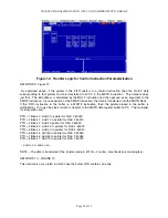
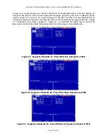
Network 4 is the base XMIT instruction. As illustrated above, the data table is filled when the drum timer
of Segment 3 network 2 counts between 1 and 10 (which are the cyclic read instructions. An optional
UPCTR counts the good transmissions (which is good for keeping track of communication percentage
failures) over the radio network. This is used with the next network in the segment to keep track of the
type of failures occurring during troubleshooting of the program. The Ladder Logic follows and is
illustrated in Figure 33.
Summary of Contents for REL 356
Page 23: ...ABB REL 356 Current Differential Protection 1 10 Product Overview and Specifications ...
Page 83: ...ABB REL 356 Current Differential Protection 3 36 Settings and Application ...
Page 127: ...ABB REL 356 Current Differential Protection 5 28 Testing ...
Page 186: ...LINE SECTIONALIZING USING A PLC AND ABB PROTECTIVE RELAY Page 49 of 53 ...
Page 187: ...LINE SECTIONALIZING USING A PLC AND ABB PROTECTIVE RELAY Page 50 of 53 ...
Page 188: ...LINE SECTIONALIZING USING A PLC AND ABB PROTECTIVE RELAY Page 51 of 53 ...
Page 189: ...LINE SECTIONALIZING USING A PLC AND ABB PROTECTIVE RELAY Page 52 of 53 ...

