—
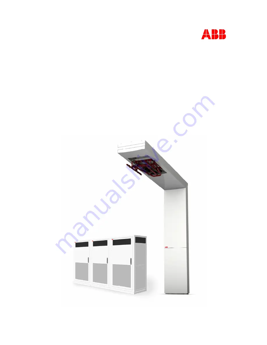
INSTALLATION GUIDE
HVC-PD E-Bus Charger
Installation Guide for NA products
Version 1.2
Page 1: ... INSTALLATION GUIDE HVC PD E Bus Charger Installation Guide for NA products Version 1 2 ...
Page 2: ...ed in this document The information in this document is subject to change without notice and should not be construed as a commitment by ABB ABB assumes no responsibility for any errors that may appear in this document In no event shall ABB be liable for direct indirect special incidental or consequential damages of any nature or kind arising from the use of this document nor shall ABB be liable fo...
Page 3: ...V1 2 Document No 6AGA000008 0629 EN Date 06 30 2022 Page 3 of 146 Version control Version Date Remarks 1 0 20 5 20201 First release 1 1 23 09 2021 Changed figures cabinet and added notice for WiFi device 1 2 30 06 2022 Updated based on NA requirements ...
Page 4: ...9 2 1 7 Charge pole 19 2 2 Accessories 20 2 2 1 Foundation for Power Cabinet 20 2 2 2 Foundation for Charge pole construction 21 2 2 3 Communication glass fiber cable 22 2 2 4 RFID unit 23 2 3 Project planning 24 3 Preparation 25 3 1 About preparation 25 3 2 Permits 26 3 2 1 Power connection 26 3 2 2 Construction permit 26 3 2 3 Internet access 26 3 3 Upgrade grid 27 3 4 Location 27 3 5 Geometry o...
Page 5: ... 5 5 1 Connect Power Cabinet to foundation 60 5 5 2 Open the door of the Power Cabinet 62 5 5 3 Move the sliding plate of the guidance plates of the cabinet 63 5 5 4 Route cables through guidance plates 63 5 5 5 Move sliding plates of the guidance plates of the cabinet 64 5 5 6 Install border covers of the Power Cabinet 65 5 5 7 Install border covers of metal frame foundation 65 5 6 Connect AC pow...
Page 6: ... Connect the DC power input cables 107 5 16 7 Connect the DC power input cables in Junction Box 109 5 16 8 Connect the AC utility power cable from Power Cabinet 111 5 16 9 Connect the communication cable from the Power Cabinet 112 5 16 10 Connect the WiFi cable 112 5 16 11 Connect the RFID cables 113 5 16 12 Connect the Interlock cable from the Power Cabinet 114 5 16 13 Connect the other cables to...
Page 7: ...ion Box 132 D Dimensions Charge pole 133 E Clearance and vertical working range of the pantograph 135 F Dimensions Concrete Foundation Power Cabinet 136 G Dimensions Metal Foundation Power Cabinet 138 H Dimensions Concrete Foundation Pole 140 I Power Cabinet Outline with Foundation 141 J Signal 142 K Ground overview of the system 145 ...
Page 8: ...thin a limited area NOC ABB Network Operating Centre remotely checks the correct functioning of the charger OPP Charge Is a trade name of fast charging method for electric vehicles Owner The legal owner of the charger Pantograph The mechanical contact linkage of the charger through which the DC charge power is electrical transported to the electrical vehicle PD Panto Down A charge system where the...
Page 9: ...any damage that has been caused by not or incorrectly following and executing the instruction described in this manual 1 2 Intended document users This document is intended to be used by Customers who purchased a HVC PD E Bus Charger or are in the process of ordering and want to know in more detail how it has to be installed Contractors who are responsible for site preparation and or installation ...
Page 10: ...ired To operate the charge station with the protective devices installed and to make sure all protective devices are correctly installed after carrying out installation or maintenance To write an emergency plan that instructs people what to do in case of emergency To prepare the site where the charge station will be installed according to the requirements described in this guide To make sure that ...
Page 11: ...nce on the requirements for safe operation of mobile cranes ML 03 9Akk104941D0113 WARNING Personal safety PPE Always wear a safety helmet safety gloves and safety shoes when you do the lifting and tilting work WARNING Make sure that personnel cannot be crushed or become trapped during lifting and tilting work Lifting activities It is a legal requirement that all activities involving lifting equipm...
Page 12: ...any installation disassembly repair or replacement of components 2 Do a voltage check and make sure that the electrical power is disconnected from the system 3 Only ABB certified technicians are permitted to commission the HVC PD E Bus Charger 4 When the system is in an open or dangerous condition do not allow unqualified persons to go near it Instruct and warn people about the potential harmful h...
Page 13: ...ng non reusable parts of the HVC PD E Bus Charger 1 6 Cyber Security Disclaimer This product is designed to be connected to and to communicate information and data via a network interface It is customer s sole responsibility to provide and continuously ensure a secure connection between the product and customer network or any other network as the case may be Customer shall establish and maintain a...
Page 14: ... Contact information ABB in your country Please contact ABB in your country for sales delivery and service information ABB EV Infrastructure global ABB EV Infrastructure Address Heertjeslaan 6 2629 JG Delft The Netherlands Telephone 31 88 440 46 00 Mail info evi nl abb com Write down here your local ABB contact details ...
Page 15: ...ending on the project and location of installation which dictates whether these parts are needed ABB offers a standard delivery system configurations with a DC charge power of 150 300 or 450 kW Additional needed components can be ordered separately and are not part of the standard delivery See section Accessories on Page 20 2 1 1 Standard HVC PD 150 kW E Bus Charger system The following parts are ...
Page 16: ...Fi communication unit for the bus Pre mounted cable set for inside the pole Transport and lifting tools 2 1 3 Standard HVC PD 450 kW E Bus Charger system The following parts are provided for this system configuration 1x HVC Panto Down 150 kW primary power cabinet 1x fold out HVC PD charge pole set 150 450kW UL ABB6AGC100126 or HVC PD charge pole set 150 450kW UL BAA ABB6AGC100125 including 1x ACS ...
Page 17: ...4 Power Cabinet Outside view of the Power Cabinet A Base cover D 3G Antenna B Air outlet E Air inlets also on the left and back side C Door F Door handle lock Inside view of the Power Cabinet A AC Fuses D Data communication connection B AC Power connection E Display only present in HVC 150 C Guidance plate of the cables ...
Page 18: ... 1 5 ACS Control Module Outside view of the ACS Control Module A Door B Locks C WiFi coax connector D In and outputs for cables from Power Cabinet and to pantograph E In and outputs DC power cables Inside view of the ACS Control Module A Communication connection B Connection block C Protection cover for DC contactors ...
Page 19: ...6 Junction Box Outside view Junction Box A Cover B In and outputs DC power cables C Output DC OVP sensing cable 2 1 7 Charge pole Outside view Charge pole A Door B Emergency button EMO C Charge state indicator light with light sensor beacon D Pantograph installation specific E WiFi communication unit F RFID unit optional ...
Page 20: ...essories The following parts can be ordered at the time of the initial order or afterwards Contact ABB Sales department see Contact information on Page 14 for contact details 2 2 1 Foundation for Power Cabinet for reference only Concrete foundation NOTICE Concrete foundations for power cabinet are not sold in NA Designs are available in Appendix E and must be manufactured by installer not manufact...
Page 21: ...and side entry A Foundation B Front border cover C Rear border cover Amount Part number Description 1 2CEB489802R0001 HPC175 HVC150 MET FOUND KIT 8IN NAM 2 2 2 Foundation for Charge pole construction Concrete foundation The concrete foundation can be used to install the Charge pole construction on soil NOTICE No charge pole foundation in NA Designs are available in Appendix G and must be manufactu...
Page 22: ...ch C Individual optical fibers length is 59 10 Inch Amount Part number Description 1 OM3 or greater prefabricated OM3 PCF or fiberglass multimode 850 nm optic cable with 8 fibers 4 for spare with B FCO ST connectors for each cable If glass fiber cable is not supplied by ABB then gland dimensions listed in section Gland layout of the ACS Control Module on Page 106 must be followed Please note that ...
Page 23: ... 630 131xx RFID RFU63x Sick 1 SSL 2J04 G10ME part 6030928 RFID Ethernet cable 10 m male connector M12 4 pin straight D coded male connector RJ45 8 pin straight Sick 1 2070427 RFID Power cable 10 m female connector M12 17 pin straight A coded Sick The RFID unit is available for the following regions xx 00 Europe Saudi Arabia South Africa 01 USA Canada Mexico 02 Australia 03 India 04 Brazil 05 China...
Page 24: ...the contractor can do the civil and electrical works See About preparation on Page 25 B Construction The contractor does all civil and electrical works See About construction on Page 38 C Placement and Connection The location is mechanically and electrically ready to receive the HVC PD E Bus Charger See About placement and connection on Page 54 D Commissioning The delivery department will bring th...
Page 25: ...rical installation work The contractor is responsible for all construction documentation of the site among other things drawings calculations certifications licenses and test reports The location of the HVC PD E Bus Charger must be chosen See section Location on Page 27 and section Geometry of infrastructure on Page 28 A3 Get permits Take care of all permits and local regulations See section Permi...
Page 26: ...t the requirements described in section Electrical installation on Page 36 3 2 2 Construction permit The installation of the HVC PD E Bus Charger requires the following construction work A solid base Work permit Cable conduits for cables between the power distribution board and the Power Cabinet Usually these cable conduits are installed below ground Cable conduits for cables between the Power Cab...
Page 27: ...the following requirements The charging system should not be installed in the hazardous location identified per the standard ANSI API RP 500 2012 Recommended Practice for Classification of Locations of Electrical Installations at Petroleum Facilities Classified as Class I Division 1 and Division 2 The height is not more than 6561 68 ft above sea level The HVC PD E Bus Charger must not be immersed ...
Page 28: ...e rear side when both left and right side have a minimum free space of 3 94 Inch 3 94 Inch or 0 Inch at the left side if another Power Cabinet is placed next to it 3 94 Inch or 0 Inch at the right side if another Power Cabinet is placed next to it 47 24 Inch at the front side in order to open the front door If the cabinet is placed inside a room consider extra free space in front of the open door ...
Page 29: ...revent snow sand or dust from blocking the inlets and outlets Specifications for inside installation of the Power Cabinet Airflow required for one cabinet 853 44 CFM Maximum allowed pressure drop 0 0435113 PSI If the pressure drop of the room is higher than 0 0435113 PSI an extra fan should be placed Contact associated Project Manager or Sales representative see Contact information on Page 14 for ...
Page 30: ...hen the sides are free with 0 Inch distance Door on front side must be kept accessible recommended 47 24 Inch See also Required space for the Power Cabinet on Page 28 3 5 3 Required space for the Charge pole The Charge Pole requires a space of 57 91 x 49 80 Inch This space is calculated as follows An Charge Pole footprint of 41 95 x 14 61 Inch The following free space 7 87 Inch at the rear side 3 ...
Page 31: ...h the bus so that the pantograph can make physical contact with the charge interface rails on the roof of the bus In general the bus has a certain freedom degree to position under the pantograph Z axis 23 62 11 81 Inch longitudinal axis Y axis 19 69 9 84 Inch transversal axis X axis 45 28 Inch vertical axis When the road is horizontal and the top of road TOR is flat no wear Compensation of angles ...
Page 32: ... position in sideways direction of the bus The minimum distance is and the maximum between the front of the pole and side of the bus is 35 43 Inch to 70 87 Inch respectively The picture below shows how to calculate on an easy matter the position of the pantograph measured middle of the collector head within the Charge Pole with respect to the position of the bus Be aware this is in case the road i...
Page 33: ... The pole can be placed on the left side or on the right side driver side of the bus This must be communicated with ABB before ordering the Charge Pole This will also be noted by ABB during the site survey for the placement of the pole Contact ABB Sales department see Contact information on Page 14 for contact details The hinge point of the pantograph s arms is always located on the right side of ...
Page 34: ...ad sideways direction is 3 5 including the kneeling of the bus This will shift the top of the bus 7 87 Inch relative to the center of the bus So the displacement caused by the road angle should be taken into account calculating the position of the Charge Pole with respect to the bus It is possible to adjust the angle in X axis see section Pantograph X axis angel adjustment on Page 103 ...
Page 35: ...talled on the location This will also be noted by ABB during the site survey for the placement of the pole Contact ABB Sales department see Contact information on Page 14 for contact details The installation can handle a road inclination smaller than 2 5 without any modification to the position of the pantograph When the road inclination is between 2 5 and 6 0 the position of the pantograph must b...
Page 36: ...eter of the electrical conductor maximum cross section is 240 mm2 500 MCM in the AC power cable depends on the length and method of installation This must be determined by your contractor 3 8 Civil installation DC power cables AC utility power cable GND wire and data cables must be routed between the Power Cabinet and the Charge control set The DC power cables must be installed in separate cable c...
Page 37: ...the location of all the cables in the ground between the Power Cabinet and the Charge control set The routing of the cables can be found easily in the future for example to prevent damage by excavation work 3 9 Lightning protection One electrode ground rod of maximum 10 Ω must be placed into the earth near the pole foundation In some cases also additional grounding is required at the Power Cabinet...
Page 38: ...e are shown in the figure below B1 Civil engineering works Construction of the foundation See section Construct foundation of the Power Cabinet on Page 39 and section Construct foundation of the Charge pole on Page 44 Installation of the cables See section Cabling on Page 49 Construction of the bus stop surrounding See section Geometry of infrastructure on Page 28 B2 Electrical engineering works S...
Page 39: ...te foundation Power Cabinet Solid floor 1 Use a metal frame foundation to guide the cables from the cabinet to the cable duct This foundation can be ordered separately See section Foundation for Power Cabinet on Page 20 For detail drawings see Appendix E Dimensions metal frame foundation Power Cabinet 2 The Power Cabinet is installed directly on a solid floor through which the floor is accessible ...
Page 40: ... protect the cables 1 Make a hole in the ground with at least a minimum depth of 34 84 Inch shown in the figure above 2 Fill the hole with minimum 7 87 Inch lean concrete C see figure above 3 Make sure that the conduits are routed to one of the indicated positions B The conduits must come out of the foundation with a length of about 9 84 Inch 4 Make sure that the AC power cable is routed to one of...
Page 41: ... the cabinet NOTICE This extra cable length is required to connect the AC power cable with the connectors in the Power Cabinet without problems 11 Place both cover plates on the appropriate place on the foundation 12 Secure the top cover plate with M16 bolts 4x and the front cover plate with M12 bolts 4x WARNING These cover plates are required to prevent people from falling into the foundation 13 ...
Page 42: ...t the marked positions The holes must be suitable for bolt size M16 4 Route the cables tray through one of the cable openings B 5 Align the frame A with the tapped holes 6 Insert the bolts C fitted with the washers D into the holes 7x 7 Tighten the bolts 8 Route the AC power cable through the left cable opening B Make sure that a cable length of 39 37 Inch is available above the floor for internal...
Page 43: ...le and other cables comes out of the floor within the marked area B 4 Make sure that the DC power cables come out of the floor within the marked areas C 5 For the AC and DC power cable make sure that a cable length of 3 28 ft is available above the floor for internal routing in the cabinet 6 For the other cables make sure that a cable length of 9 84 ft is available above the floor for internal rou...
Page 44: ...e floor can handle the force of the pole Contact the ABB Sales department when you want to mount the Charge pole on a concrete floor see Contact information on Page 14 for contact details The cables must be embedded in the ground with cable conduits See section Cabling on Page 49 and section Civil installation on Page 36 4 3 2 Workflow with pre fabricated concrete foundation for reference only NOT...
Page 45: ...g the hole 23 62 Inch deeper than the level of the underside of the concrete base plate The soil under the base plate has to be compacted in layers of 11 81 Inch with an advised pressure of 100 kPa Level the soil under the concrete base plate Install the concrete base plate and make sure the foundation is level The allowed tolerance angle with respect to the charging position of the bus must not b...
Page 46: ... the cables The base plate has holes for entering cables into the charging pole construction which are positioned aligned with the road The base plate must be positioned in the right way to have the cable conduits facing towards the foundation of the Power Cabinet The base plate can be installed 180 degrees to face the cable entries to the other side With preparation of the soil the concrete base ...
Page 47: ...laws are not delivered by ABB use for example Starcon Universal Lifting Claws art no 99 11590081B With the concrete base plate in position the counter weights can be installed These counter weights are needed to keep the charging pole construction up right during extreme weather conditions and to prevent the construction from tilting There are two bullet head anchors 2 5 K170D DH pouring in the co...
Page 48: ...e with a length of about 9 84 inch Cover the conduits to prevent water sand and or other materials entering the conduits Place protective cups to cover the bolt 16x The gap around the foundation can now be filled with sand in layers of 11 81 Inch each Between each layer the soil has to be compacted with an advised pressure of 100 kPa This sequence has to be repeated until the top side of the concr...
Page 49: ... 06 30 2022 Page 49 of 146 NOTICE To already fixed the sidewalk around the pole there can be placed border collar around the top of the foundation to have free access of the bolts 4 4 Cabling 4 4 1 Charge system configuration Overview electrical connections of a HVC PD 150 kW charge system ...
Page 50: ...harge system Overview electrical connections of a HVC PD 450 kW charge system Separated electrical diagrams for the different HVC PD Charge systems are available Ask associated PM or sales representative if required 6AGA000008 0617 Electrical diagram HVC PD 150 kW E Bus Charger 6AGA000008 0618 Electrical diagram HVC PD 300 kW E Bus Charger Primary Secondary Secondary ...
Page 51: ...ope of supply of ABB 2x 4x or 6x DC power cables depending on system configuration 1x DC OVP Sensing cable between Junction Box and ACM 1x GND cable 1x AC utility power cable 1x Interlock cable 4x communication cables 8x glass fiber 4 fibers are required 4 are for spare The 8x glass fiber cable is a special cable that should be sourced locally Use local regulations and datasheet of the manufacture...
Page 52: ...esistant Nominal Voltage Uo U 600 1000 Vac 900 1500 Vdc 450 750 Vac 450 750 Vac Test Voltage 6 kV 4 kV 4 kV Ambient Temperature range 40ºC to 80ºC permissible conductor operating temperature 90 C 40ºC to 70ºC 40ºC to 80ºC Core identification gn ye Color Acc to IEC 60446 Data cables Functional description Interlock cable CAN cable Number of twisted pairs 2 x 2 1 x 2 Cross section 18 14 AWG 20 18 AW...
Page 53: ...at a cellular availability test is performed prior to construction to ensure there is reasonable signal quality to at least one of the above mentioned operators 4G LTE bands 2 1900 MHz 4 1700 2100MHz or 12 700 MHz The signal strength must be greater than 85dbm and should be measured with a cellular network signal meter such as a Squid 4G or Sure Call device Handheld mobile phones are not recommend...
Page 54: ...y C1 Route the cables on Page 55 C2 Unpack on Page 55 C3 Move Power Cabinet to position on Page 57 and Install Power Cabinet onto the foundation on Page 60 C4 Connect the AC power cable on Page 66 Connect the DC power cables on Page 73 and Connect the communication fiber cables on Page 85 C5 Unpack the Charge Pole on Page 87 C6 Move the Charge pole to position on Page 88 Install Charge Pole onto t...
Page 55: ...able 5 For the DC power cables make sure that a cable length of 39 37 Inch is available above the surface for internal routing in the cabinet 6 For the other cables make sure that a cable length of 118 11 Inch is available above the surface for internal routing in the cabinet NOTICE This extra cable length is required to connect the cables with the connectors in the Power Cabinet without problems ...
Page 56: ...Guide Document V1 2 Document No 6AGA000008 0629 EN Date 06 30 2022 Page 56 of 146 The product is delivered by a transport company at the confirmed date of delivery 1 Make sure that the Power Cabinet has not been shaken or tilted over 30 ...
Page 57: ...the nuts A at the four corners 5 4 Move Power Cabinet to position There are two options to move the Power Cabinet from the delivery truck to the location Use a hoist to lift the cabinet from the top See Move cabinet with a hoist on Page 58 Use a forklift truck to lift the cabinet from the bottom See Move cabinet with a forklift truck on Page 59 Preconditions All packaging material is removed from ...
Page 58: ...o its position is not covered by the warranty CAUTION Do not use a compressor to clean the Power Cabinet Use a vacuum cleaner 1 Use one of the two options to move the Power Cabinet to the foundation 2 When the Power Cabinet is about 19 69 Inch above its location continue the installation procedure with Install Power Cabinet onto the foundation on Page 60 5 4 1 Move cabinet with a hoist A Swivel ey...
Page 59: ...s A minimum of two persons is required one person to operate the forklift truck the other person to guide the Power Cabinet to its location 1 Place wooden slats with a thickness of about 0 39 to 0 59 Inch and a width equal to the width of the fork of the forklift truck on both forks 2 Move the forks of the forklift truck next the gaps at the rear of the Power Cabinet 3 Move the Power Cabinet to th...
Page 60: ... Cabinet bag with parts The Power Cabinet is about 19 69 Inch above its location DANGER Make sure that the main switch of the power supply group for the product is set to the OFF position Do a voltage check to make sure that the electrical power is disconnected from the system Secure against resetting WARNING Make sure that personnel cannot be crushed or become trapped while moving the Power Cabin...
Page 61: ... do not trap the cables C 3 Make sure that the cabinet is aligned with the tapped holes D 4 Insert the M16 bolts A fitted with the washers into the holes in the corners 4x NOTICE A minimum of three M16 bolts are need to applied to securely mount the Power Cabinet onto the foundation In case of placing two Power Cabinets next to each other and 3 94 Inch distance against the wall then one Power Cabi...
Page 62: ... 06 30 2022 Page 62 of 146 6 Remove the swivel eye bolts or lifting loops A 7 Place the cover caps B in the holes 4x 5 5 2 Open the door of the Power Cabinet Preconditions Key that were removed from the Power Cabinet bag with parts 1 Unlock the handle B 2 Use the handle B to open the door A ...
Page 63: ...of the guidance plates of the cabinet Preconditions Tools spanner size 13 1 Loosen the bolts A 2 Move the sliding plate B of the 2 guidance plates 5 5 4 Route cables through guidance plates 1 Route the cables A through the right guidance plates B 2 Make sure that there is sufficient cable length to reach the connectors at the top of the cabinet ...
Page 64: ... of 146 NOTICE A length of 118 11 Inch is required because the connection of the cables with the connectors in the Power Cabinet is at the middle of the cabinet 5 5 5 Move sliding plates of the guidance plates of the cabinet Preconditions Tools spanner size 13 1 Move the sliding plates B 2 Tighten the bolts A ...
Page 65: ...m front of the Power Cabinet by aligning the four bolts at the back side of the front cover A with the holes in the bottom front 2 Put the rear cover B against the rear front of the Power Cabinet 3 Insert the M5 bolts C into the holes 8x 4 Tighten the bolts 5 5 7 Install border covers of metal frame foundation NOTICE Only applicable when the Power Cabinet is placed on a metal frame foundation The ...
Page 66: ...the Power Cabinet 3 Put the side border covers D against the sides of the Power Cabinet 4 Insert the M5 bolts C into the holes 8x 5 Tighten the bolts 5 6 Connect AC power cable and GND wires Power Cabinets 5 6 1 Remove the protection covers Preconditions Tools cross head screwdriver 1 Remove the protection plate A by loosening the screws B 2 Put the protection plate and screws in a safe location a...
Page 67: ...location as it will be installed again later on 5 6 2 Connect the GND wire of the AC power cable Preconditions Tools wire cutter wire stripper pliers cable lug spanner size 19 torque wrench size 19 DANGER Make sure that the main switch of the power supply group for the product is set to the OFF position Do a voltage check to make sure that the electrical power is disconnected from the system Secur...
Page 68: ...of the GND wire 4 Attach a cable lug A to the end of the GND wire B 5 Remove the M12 bolt nut and washers from the GND rail 6 Fit the bolt C with toothed washer D the GND wire B and the contact washer E 7 Insert the bolt fitted with the GND wire into the GND rail 8 Screw from the bottom of the GND rail a toothed washer D and a nut F on the bolt C 9 Tighten the bolt nut connection with a tightening...
Page 69: ... too tight or too loose 2 Strip the insulation on the required length specified by the used lug from the end of the wire B 3 Attach cable lugs A at the end of the wires 4 Remove the nuts and washers C from the bolts M12 of connector block D 5 Insert the 3 wires B with the nuts and washers onto the bolts of connector block D From left to right L1 brown L2 orange L3 yellow 6 Tighten the nuts C with ...
Page 70: ...screwdriver 1 Take the 3 protection covers that was removed in Remove the protection covers on Page 66 2 Place the protection covers D back on the connector blocks C 3 Take the protection plate and the screws that were removed in Remove the protection covers on Page 66 4 Place the protection plate A back over the main switch and connector blocks and secure the plate by the screws B ...
Page 71: ...e 19 torque wrench size 19 1 Cut the wire of the lightning protection cable to the correct length to reach the GND rail Do not make the wire routing too tight or too loose 2 Strip 0 79 Inch of the insulation from the end of the wire 3 Attach a wire end ring A to the end of the lightning protection wire B 4 Remove the M12 bolt nut and washers from the GND rail 5 Fit the bolt C with toothed washer D...
Page 72: ...Cut the GND wire of the power cable to the correct length to reach the GND rail Do not make the wire routing too tight or too loose 2 Strip 0 79 Inch of the insulation from the end of the GND wire 3 Attach a wire end ring A to the end of the GND wire B 4 Remove the M12 bolt nut and washers from the GND rail 5 Fit the bolt C with toothed washer D the GND wire B and the contact washer E 6 Insert the...
Page 73: ...wire 3 Attach a wire end ring A to the end of the GND wire B 4 Remove the M12 bolt nut and washers from the GND rail 5 Fit the bolt C with toothed washer D the GND wire B and the contact washer E 6 Insert the bolt fitted with the GND wire into the GND rail 7 Screw from the bottom of the GND rail a toothed washer D and a nut F on the bolt C 8 Tighten the bolt nut connection with a tightening torque...
Page 74: ...ect lengths to reach the connectors Do not make the wire routing too tight or too loose 2 Strip the insulation on the required length specified by the used lug from the end of the wire B 3 Attach cable lug A at the end of the wires 4 Remove the nuts and washers C from the bolts M12 of connector block D and E 5 Insert the DC wire marked by red heat shrink with the nuts and washers onto the bolts of...
Page 75: ...e DC connector blocks and secure the plate by the screws B 4x 5 8 Connect AC utility power Interlock and CAN cables Power Cabinet Preconditions Tools wire cutter wire stripper pliers screwdriver ferrules crimp pliers DANGER Make sure that the main switch of the power supply group for the product is set to the OFF position Do a voltage check to make sure that the electrical power is disconnected fr...
Page 76: ...ble route inside the cabinet 5 8 2 Connect the AC utility power cable NOTICE The AC utility power cable for the ACS Control Module is only connected within the HVC 150 Power Cabinet see for more details section Cabling on Page 49 A Terminal block B AC utility power cable 1 Move the cable towards the terminal block A 2 Strip 0 43 Inch of the insulation from the ends of the wires 3 Crimp a ferrule o...
Page 77: ...the White and Brown wire 4 Ensure that the unused wires the Green and Yellow wire are protected so that they cannot touch metal parts 5 Make a wire connection between pin X286 6 and X286 7 and pin X286 10 and X286 11 6 Loosen the connector screws 7 Insert the wires into the connectors see table below Functional description Connector Wire number Interlock In X286 15 Brown Interlock Out X286 14 Whit...
Page 78: ...own wire 4 Ensure that the unused wires the Green and Yellow wire are protected so that they cannot touch metal parts 5 Loosen the connector screws 6 Remove the wire connection between pin X286 6 and X286 7 if present 7 Insert the wires into the connectors see table below Functional description Connector Wire number Interlock In ACM X286 15 Brown Interlock Out ACM X286 14 White Interlock GND ACM X...
Page 79: ...the Green and Yellow wire are protected so that they cannot touch metal parts 5 Make a wire connection between pin X286 6 and X286 7 and pin X286 10 and X286 11 6 Loosen the connector screws 7 Insert the wires into the connectors see table below Functional description Connector Wire number Interlock In primary HVC 150 X286 14 Brown Interlock Out primary HVC 150 X286 15 White Interlock GND primary ...
Page 80: ...of the White and Brown wire 4 Ensure that the unused wires the Green and Yellow wire are protected so that they cannot touch metal parts 5 Loosen the connector screws 6 Remove the wire connection between pin X286 6 and X286 7 and pin X286 10 and X286 11 if present 7 Insert the wires into the connectors see table below Functional description Connector Wire number Interlock In ACM X286 15 Brown Inte...
Page 81: ... onto the end of the White and Brown wire 4 Ensure that the unused wires the Green and Yellow wire are protected so that they cannot touch metal parts 5 Make a wire connection between pin X286 7 and X286 8 6 Loosen the connector screws 7 Insert the wires into the connectors see table below Functional description Connector Wire number Interlock In secondary 1 HVC 150S X286 4 Brown Interlock Out sec...
Page 82: ...450 kW system A Terminal block B CAN cable to secondary 1 HVC 150S 1 Move the cable towards the terminal block A 2 Strip 0 43 of the insulation from the ends of the wires 3 Crimp a ferrule onto the end of the wire 4 Loosen the connector screws 5 Insert the wires into the connectors see table below Functional description Connector Wire color CAN H Out X286 10 Brown CAN L Out X286 11 White CAN GND X...
Page 83: ...Crimp a ferrule onto the end of the wire 4 Loosen the connector screws 5 Insert the wires into the connectors see table below Functional description Connector Wire color CAN H In to primary HVC 150 X286 1 Brown CAN L In to primary HVC 150 X286 2 White CAN GND to primary HVC 150 X286 3 or Shield Can In Shield CAN H Out from secondary 2 HVC 150S X286 16 Brown CAN L Out from secondary 2 HVC 150S X286...
Page 84: ...inal block A 2 Strip 0 43 Inch of the insulation from the ends of the wires 3 Crimp a ferrule onto the end of the wire 4 Loosen the connector screws 5 Insert the wires into the connectors see table below Functional description Connector Wire color CAN H In X286 1 Brown CAN L Out X286 2 White CAN GND X286 3 or Shield Can In Shield See also Appendix H Signal connection diagram 6 Tighten the connecto...
Page 85: ...ol Module are only connected within the primary HVC 150 Power Cabinet see for more details section Cabling on Page 49 5 9 1 Route the cable to the terminal blocks Preferred cable route 1 Route the communication fiber cable to module D1 B and D2 A Refer to the figure for the preferred cable route inside the cabinet only within the HVC 150 5 9 2 Connect the communication fiber cables Preconditions T...
Page 86: ...ber cables D onto module D1 B Rx with Td D1 Tx with Rd D1 NOTICE Four fiber cables are not connected Those fiber cables are meant for spare 4 Bind the cables together and secure the loops loosely with a piece of tak ty or ty rap CAUTION Make the loop bend radius of the fiber cables not smaller than 2 52 Inch otherwise the core of the fiber cable may break 5 10 Close the door of the Power Cabinet P...
Page 87: ...able regulations as well as environment friendly Preconditions All construction work is completed The product is delivered by a transport company at the confirmed date of delivery Equipment to set the pole in the right position during installation in all directions Crane to lift the frame of the pole The minimum load is about 3761 lb and minimum height required about 23 ft Mobile elevated work pla...
Page 88: ...re removed The protective cups to cover the bolts of the foundation are removed and the bolts are free from dust If necessary clean the bolts with a vacuum cleaner or brush The work must be carried out by at least two persons One person to operate the hoisting equipment the other to guide the Charge Pole Tools spanner size 36 DANGER Make sure that the main switch of the power supply group for the ...
Page 89: ...lings and place the Charge Pole beside the trailer In order not to damage the Charge Pole use a wooden beam A on which the end of the pole can rest 3 Loosening the nut bolt B 2x but do not remove those on both side of the mast boom so that the mast boom can freely rotated 4 Remove the hoisting equipment only from transport holder C 5 Lift the Charge Pole up by using slings which are only connected...
Page 90: ...obile elevated work platform spanner size 36 torque wrench size 36 DANGER Make sure that the main switch of the power supply group for the product is set to the OFF position Do a voltage check to make sure that the electrical power is disconnected from the system Secure against resetting Installation on concrete foundation A Foundation for reference only D Opening for cables B Charge Post E Bolts ...
Page 91: ...the M24 or equivalent nuts onto the bolts and place on each nut the 0 32 Inch thick washers 16x The default height between the top of the washer and foundation must be 1 97 Inch NOTICE Do not use the 0 12 Inch thick washers supplied with the foundation The nuts need to be leveled relative to the concrete foundation else you would compensate the sand settlement angle 3 Carefully position the Charge...
Page 92: ...ge 14 for contact details 8 Tighten the nuts with a tightening torque of 590 05 ft lb when no copper fat is used and with a tightening torque of 390 91 ft lb when copper fat is used 9 Screw the second M24 nuts on the bolts 16x 10 Tighten the upper nuts 11 Remove the hoisting equipment from the Charge Pole 5 14 Install mast boom onto column Preconditions Tools mobile elevated work platform torx scr...
Page 93: ... which secured the transport holder A with the column C of the Charge Pole 3 Lift up the mast boom B until it touches the column C horizontally 4 Mount the mast boom B onto the column C by using 12x M16 bolt washer washer nut connection Use 12 pieces bolts of M16 x 60 THVZ Class 8 8 and THVZ washers and nuts A torque of 169 64 ft lb has to be applied ...
Page 94: ...the transport holder A 6 Remove the transport holder A from the mast boom B by removing the bolts G and washers F 4x 7 Remove on both side the U profiles I by detaching the two M6 bolts J 8 Remove the cover plate H by detaching the M6 bolts J 9 Put the cover plate U profiles and bolts in a safe location as it will be installed again later on ...
Page 95: ... corner cover plates K 2x onto the Charge Post and tighten the M6 bolts J 8x 11 Place the bottom corner cover plates L 2x onto the Charge Post and tighten the M6 bolts L 8x 12 Place the corner U profiles M 4x on both side of the Charge Post and tighten the M6 bolts 8x 13 Place the front cover plate N onto the end of the mast boom B 14 Use M10 x 30 THVZ bolts P 2x in combination with a M10 THVZ was...
Page 96: ...allation Guide Document V1 2 Document No 6AGA000008 0629 EN Date 06 30 2022 Page 96 of 146 17 Place back the cover plate H and tighten the M6 bolts J 4x 18 Place back the U profiles I on both side and tighten the M6 bolts J 4x ...
Page 97: ...therwise there are chances the pole do not comply with local traffic regulations or the pantograph can work out of its linear zone The pole is delivered with the pantograph at its maximum reach end of the horizontal section After the pole has been erected the pantograph has to be positioned where it be needed for an effective operation Information required to preposition the pantograph during the ...
Page 98: ...63 834 806 778 750 722 694 665 637 609 581 553 525 1100 869 841 813 784 756 728 700 672 644 615 587 559 531 503 475 1150 819 791 763 734 706 678 650 622 594 565 537 509 481 453 425 1200 769 741 713 684 656 628 600 572 544 515 487 459 431 403 375 1250 719 691 663 634 606 578 550 522 494 465 437 409 381 353 325 1300 669 641 613 584 556 528 500 472 444 415 387 359 331 303 275 1350 619 591 563 534 506...
Page 99: ...4 1363 1391 1419 1447 1475 1503 1100 1059 1087 1115 1144 1172 1200 1228 1256 1284 1313 1341 1369 1397 1425 1453 1150 1009 1037 1065 1094 1122 1150 1178 1206 1234 1263 1291 1319 1347 1375 1403 1200 959 987 1015 1044 1072 1100 1128 1156 1184 1213 1241 1269 1297 1325 1353 1250 909 937 965 994 1022 1050 1078 1106 1134 1163 1191 1219 1247 1275 1303 1300 859 887 915 944 972 1000 1028 1056 1084 1113 1141...
Page 100: ... bolts 3 Remove the cover plates B by detaching the M6 bolts 4 Put the cover plates U profiles and bolts in a safe location as it will be installed again later on When the cover plates B are removed the bolts for moving the pantograph is accessible from below 5 The pantograph is suspended in the C profile of the frame G by two suspended plates with slide bearings F on each side of the pantograph T...
Page 101: ...ctions can still be made during commissioning The tensioning straps are removed after commissioning 8 When removed place back the cover plates B so that only the pantograph and the WiFi antenna are free of access and tighten the M6 bolts NOTICE Additional cover plates are included in the supplied wooden crate The additional cover plates can be used to properly sealed the bottom side of the horizon...
Page 102: ...n both side of the two V shape bolts C so the pantograph can rotate freely WARNING Don t remove the nuts A of the two U bolts C Otherwise the pantograph can fall down 2 Loosening lock nuts C 2x on both side of the locking bolts B 3 Turn both bolts B outwards but do not remove those so that the pantograph can freely rotated 4 Adjust the pantograph with help of the included level tool in the correct...
Page 103: ...a safe location as it will be installed again later on 3 Rotate the pantograph to the correct angle position 4 Install the M8 bolts in the new angle position slots 5 Tighten M8 bolts A 4x 5 16 Installation of the cables inside Charge Post DANGER Make sure that the main switch of the power supply group for the product is set to the OFF position Do a voltage check to make sure that the electrical po...
Page 104: ...y required when the lower front cover plate is delivered assembled onto the pole Normally the lower front cover plate E and both U profiles C are delivered separately with the pole 2 Remove on both side the U profiles C by detaching the two M6 bolts D 3 Remove the cover plate E by detaching the M6 bolts F 4 Put the cover plate U profiles and bolts in a safe location as it will be installed again l...
Page 105: ...r E 6 Insert the bolt fitted with the GND wire into the GND rail 7 Tighten the bolt with a tightening torque of 11 ft lb 5 16 3 Install lightning protection Preconditions Tools wire cutter wire stripper pliers cable lug spanner size 13 torque wrench size 13 1 Cut the wire of the lighting protection cable to the correct length to reach the lighting protection connection Do not make the wire routing...
Page 106: ... Ethernet 6 5 10 mm 0 20 0 39 Inch EMO switch 7 5 10 mm 0 20 0 39 Inch Beacon 8 5 10 mm 0 20 0 39 Inch Not used 9 5 10 mm 0 20 0 39 Inch Temperature sensor 10 10 17 mm 0 39 0 67 Inch RFID Power cable 11 13 21 mm 0 51 0 83 Inch Communication fibers 12 13 21 mm 0 51 0 83 Inch ACS Control 13 13 21 mm 0 51 0 83 Inch PE GND 14 27 35 mm 1 07 1 38 Inch DC In from HVC 150 primary 15 27 35 mm 1 07 1 38 Inc...
Page 107: ...pper pliers cable lugs 3x spanner size18 torque wrench size 18 NOTICE Ensure that the DC cables during mounting do not hit the PCBAs on the door of the ACS Control Module When these cables hit the PCBAs the PBCAs can be damaged It is advised to protect the PCBAs during mounting of the DC cables To prevent damage of the PCBAs in the ACS Control Module 1 Cut the DC cables at 15 75 Inch from the bott...
Page 108: ... by the used lug from the end of the wire B 7 Insert the DC power cables into the right cable gland 14 15 and 20 see picture above and section Gland layout of the ACS Control Module on Page 106 8 Attach cable lug A at the end of the wires 9 Remove the nuts and washers C from the bolts of the DC contactor connectors 10 If present remove the sense wires from the bolts of the DC contactor connectors ...
Page 109: ... with a tightening torque of 22 ft lb 14 Place the protection cover back on the DC contactors 15 Hand tighten the screws of the protection cover 16 Tighten the cable gland s nut to secure the DC power cables 5 16 7 Connect the DC power input cables in Junction Box Preconditions Tools wire cutter wire stripper pliers cable lugs 3x spanner size18 torque wrench size 18 cross head screwdriver 1 Loosen...
Page 110: ...nd of the wires D 8 Remove the M12 bolts washers and nuts from the bus bar G 9 Fit the bolt E with flat washer F and the wire D 6x 10 Insert the bolt fitted with the wire into the bus bar G 6x 11 Secure the bolt E onto the bus bar G with the spring washer H and the nut I 6x 12 Tighten the bolts E and nuts I with a tightening torque of 59 ft lb 13 Tighten the cable gland s nut to secure the DC powe...
Page 111: ...able routing too tight or too loose 4 Tighten the nut of the gland to secure the AC utility power cable 5 Strip the insulation from the AC utility power cable A 6 Cut the wires of the AC utility power cable A to the correct lengths to reach the connectors Make sure the GND wire is longer than the other wires 7 Strip 0 43 Inch of the insulation from the ends of the wires 8 Crimp a ferrule onto the ...
Page 112: ...otection covers from the optical connectors 3 Connect the two Ethernet fiber cables C onto module A Rx with Td U5 Tx with Rd U5 4 Connect the two CAN bus fiber cables D onto module B Rx with Td U7 Tx with Rd U7 5 Bind the cables together and secure the loops loosely with a piece of tak ty or ty rap CAUTION Make the loop bend radius of the fiber cables not smaller than 2 52 Inch otherwise the core ...
Page 113: ...e RFID module is not present Preconditions Tools wire cutter wire stripper pliers screwdriver ferrules crimp pliers 1 Loosen and remove the cable gland s 5 and 10 nuts for the RFID Ethernet and the RFID Power cables respectively 2 Slide the cable gland s nuts over the RFID Ethernet and RFID Power cable 3 Route the RFID Ethernet cable through gland 5 to module U10 A 4 Insert the RJ45 connector B of...
Page 114: ... from the ends of only the Brown and Blue wire 10 Crimp a ferrule onto the end of the Brown and Blue wire 11 Cut the other wires except the Brown and Blue wire at the end of the striped insulation of the cable 12 Loosen the connector screws 13 Insert the wires into the correct connectors see table below Functional description Connector Wire color 24 V RFID X4 41 Brown GND RFID X4 42 Blue 14 Tighte...
Page 115: ...ires of the Interlock cable B to the correct lengths to reach the connectors 7 Strip 0 43 Inch of the insulation from the end of wires 8 Crimp a ferrule onto the end of the wires 9 Loosen the connector screws 10 Insert the wires into the correct connectors see table below Functional description Connector Wire number Ext Interlock In X4 1 White Ext Interlock Out X4 2 Brown DC Guard A X4 5 Green DC ...
Page 116: ...ength do not make the cable routing too tight or too loose 4 Tighten the nuts of the glands to secure the cables 5 Strip the insulation from the cables 6 Cut the wires of the cables to the correct lengths to reach the connectors 7 Strip 0 43 Inch of the insulation from the ends of the wires 8 Crimp a ferrule onto the end of the wire NOTICE Only for the Interlock cable Use only the White and Brown ...
Page 117: ... 1 CP 10 Wire 2 PE X3 X4 ACS Control cable 1 Wire 1 ACS 24V 2 Wire 2 ACS 24V 3 GND green yellow GND 11 Wire 3 ACS Extend Retract Out 12 Wire 4 ACS Magn Reed In 13 Wire 5 ACS Supply Retract Out 14 Wire 6 ACS Retracted In 15 Wire 7 ACS Magn Supply Out 16 Wire 8 ACS GND_B 17 Wire 9 ACS Extended In X4 EMO cable 19 Wire 1 EMO S1 20 Wire 2 EMO S1 21 Wire 3 EMO S2 22 Wire 4 EMO S2 X4 Beacon cable 23 Wire...
Page 118: ...ol Module Preconditions Key 1 Close the door A 2 Close the locks B 5 16 15 Place back cover plate and close door of the Charge Pole Preconditions Key A minimum of two persons is required Tool torx screwdriver size 2163TX T30 1 Place back the cover plate E and tighten the M6 bolts F 4x 2 Place back the U profiles C on both side and tighten the M6 bolts D 4x ...
Page 119: ...lose the door A of the Charge Pole 4 Locking the two lockers B 5 17 Install cover plates Preconditions Packing foil are removed from the plate work Tools torx screwdriver size 2163TX T30 1 Put the two U profile cover plates B against the bottom of the column A 2 Insert the M6 bolts C into the holes 4x 3 Tighten the bolts ...
Page 120: ...ntering into cable ducts the space between the foot print of the vertical frame and the concrete foundation has to be filled with non shrink grout 1 Place a mold around the foot print of the column The border collar suggested in Workflow with pre fabricated concrete foundation on Page 44 can be used as mold Make sure the mold is sealed watertight 2 Prepare the grouting mortar NOTICE Read and follo...
Page 121: ...al contractor Local contractor must be perform the megger test of the conductors and provide ABB with the test report prior to commissioning Before the service engineer can start the following conditions must be met All installation work is done Grid power is available A local technician is present for assistance and to switch the power on Mobile elevated work platform available to check all the c...
Page 122: ...in circumstances ABB will be represented by a project engineer The CAF contains information about the project number location charger type a checklist about the delivery the commissioning SAT checklist list of remaining items After the CAF has been signed the customer support will be handled by the ABB Service department If there are any remaining items they can be noted on the CAF document togeth...
Page 123: ... group for the product is set to the OFF position Do a voltage check to make sure that the electrical power is disconnected from the system Secure against resetting 7 2 Cleaning of the cabinet The Power Cabinet and Charge pole is powder coated This coating must be kept in good condition Clean the Power Cabinet and Charge pole three times a year in the following way Remove rough dirt by spraying wi...
Page 124: ... to rain it is sufficient to clean it twice a year CAUTION Do not apply high pressure water jets Water may leak into the Power Cabinet If a high pressure water jet has been used make sure that the inside of the Power Cabinet is dry Only use cleaning agents with a pH value between 6 and 8 Do not use cleaning agents with abrasive components Do not use abrasive tools ...
Page 125: ...odule Short Circuit Capacity 65 kA DC output Maximum output power 150 kW Output voltage range 150 850 V DC Maximum output current 225 A DC 8 2 Electrical specification complete 300 kW system Input Supply voltage 3 phase GND L1 L2 L3 Input voltage range 480 277 V AC 10 Input frequency range 600 347 V AC 10 15 Canada version Input frequency range 60 Hz 1 Maximum power dissipation 348 kVA Power facto...
Page 126: ...put current 600 A DC 8 4 Mechanical data Mechanical specification Power Cabinet Dimensions H x W x D 82 36 x 46 06 x 30 32 Inch Including swivel eye bolts Weight 2954 19 lb Volume 114114 40 in3 Dimensions including packaging H x W x D 88 58 x 47 24 x 31 50 Inch Weight including packing 3086 47 lb Weight concrete foundation 2866 00 lb Mechanical impact protection IK10 Housing Stainless steel 430 Me...
Page 127: ...n condensing Altitude 6561 68 ft max Storage conditions Indoors dry Environment specification Charge pole Ingression protection IP54 Temperature range Operation 35 ºC to 45 C Temperature range Storage 10 ºC to 70 C Humidity 5 to 95 RH non condensing Altitude 6561 68 ft max Maximum operational wind speed 44 7 mph 8 Bft Maximum deflection 89 5 mph 14 Bft Storage conditions Indoors dry CAUTION Warran...
Page 128: ...nsions ACS Control Module C Dimensions Junction Box D Dimensions Charge pole E Clearance and vertical working range of the pantograph F Dimensions Concrete Foundation Power Cabinet G Dimensions Metal Foundation Power Cabinet H Dimensions Concrete Foundation Pole I Power Cabinet Outline with Foundation J Signal connection diagram K Ground overview of the system ...
Page 129: ...HVC PD E Bus Charger Installation Guide Document V1 2 Document No 6AGA000008 0629 EN Date 06 30 2022 Page 129 of 146 A Dimensions Power Cabinet All sizes in mm 1 mm 0 039 Inch ...
Page 130: ...HVC PD E Bus Charger Installation Guide Document V1 2 Document No 6AGA000008 0629 EN Date 06 30 2022 Page 130 of 146 All sizes in mm 1 mm 0 039 Inch ...
Page 131: ...HVC PD E Bus Charger Installation Guide Document V1 2 Document No 6AGA000008 0629 EN Date 06 30 2022 Page 131 of 146 B Dimensions ACS Control Module All sizes in mm 1 mm 0 039 Inch ...
Page 132: ...HVC PD E Bus Charger Installation Guide Document V1 2 Document No 6AGA000008 0629 EN Date 06 30 2022 Page 132 of 146 C Dimensions Junction Box All sizes in mm 1 mm 0 039 Inch ...
Page 133: ...HVC PD E Bus Charger Installation Guide Document V1 2 Document No 6AGA000008 0629 EN Date 06 30 2022 Page 133 of 146 D Dimensions Charge pole All sizes in mm 1 mm 0 039 Inch ...
Page 134: ...HVC PD E Bus Charger Installation Guide Document V1 2 Document No 6AGA000008 0629 EN Date 06 30 2022 Page 134 of 146 During transport All sizes in mm 1 mm 0 039 Inch ...
Page 135: ...HVC PD E Bus Charger Installation Guide Document V1 2 Document No 6AGA000008 0629 EN Date 06 30 2022 Page 135 of 146 E Clearance and vertical working range of the pantograph ...
Page 136: ...HVC PD E Bus Charger Installation Guide Document V1 2 Document No 6AGA000008 0629 EN Date 06 30 2022 Page 136 of 146 F Dimensions Concrete Foundation Power Cabinet All sizes in mm 1 mm 0 039 Inch ...
Page 137: ...HVC PD E Bus Charger Installation Guide Document V1 2 Document No 6AGA000008 0629 EN Date 06 30 2022 Page 137 of 146 All sizes in mm 1 mm 0 039 Inch ...
Page 138: ...ent V1 2 Document No 6AGA000008 0629 EN Date 06 30 2022 Page 138 of 146 G Dimensions Metal Foundation Power Cabinet HxC power cabinet metal foundation 4EPY420133R1 HPC175 HVC150 MET FOUND KIN 8IN NAM 2CEB489802R0001 All sizes in mm 1 mm 0 039 Inch ...
Page 139: ...HVC PD E Bus Charger Installation Guide Document V1 2 Document No 6AGA000008 0629 EN Date 06 30 2022 Page 139 of 146 ...
Page 140: ...HVC PD E Bus Charger Installation Guide Document V1 2 Document No 6AGA000008 0629 EN Date 06 30 2022 Page 140 of 146 H Dimensions Concrete Foundation Pole All sizes in mm 1 mm 0 039 Inch ...
Page 141: ...HVC PD E Bus Charger Installation Guide Document V1 2 Document No 6AGA000008 0629 EN Date 06 30 2022 Page 141 of 146 I Power Cabinet Outline with Foundation All sizes in mm 1 mm 0 039 Inch ...
Page 142: ...HVC PD E Bus Charger Installation Guide Document V1 2 Document No 6AGA000008 0629 EN Date 06 30 2022 Page 142 of 146 J Signal connection diagram For HVC 150 kW system ...
Page 143: ...HVC PD E Bus Charger Installation Guide Document V1 2 Document No 6AGA000008 0629 EN Date 06 30 2022 Page 143 of 146 For HVC 300 kW system ...
Page 144: ...HVC PD E Bus Charger Installation Guide Document V1 2 Document No 6AGA000008 0629 EN Date 06 30 2022 Page 144 of 146 For HVC 450 kW system ...
Page 145: ...HVC PD E Bus Charger Installation Guide Document V1 2 Document No 6AGA000008 0629 EN Date 06 30 2022 Page 145 of 146 K Ground overview of the system ...
Page 146: ...HVC PD E Bus Charger Installation Guide Document V1 2 Document No 6AGA000008 0629 EN Date 06 30 2022 Page 146 of 146 NOTES ...