5-10
IM 253710-01E
Explanation
WARNING
To ensure safety, if the current to be measured exceeds 7 A (RMS), use a cable
or conductor that allows current greater than the current to be measured to flow
through it, and always connect protective grounding prior to use of this
instrument. For products shipped as of January 2004, the protective earth
terminal is located* on the rear panel.
*
If you need to confirm whether a protective earth terminal is installed, please contact the
dealer from whom you purchased the instrument.
Setting the voltage and current ranges
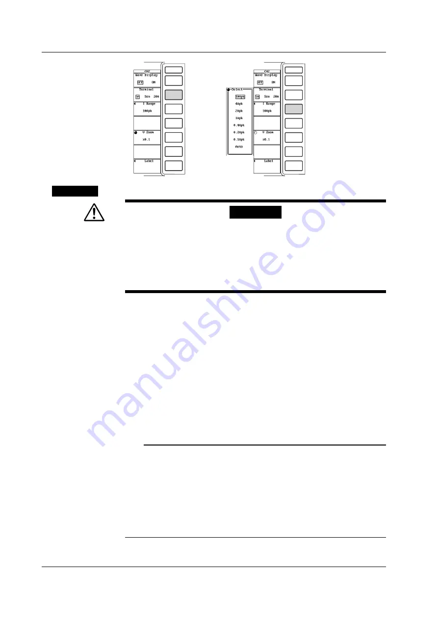
The voltage and current ranges can be set using the full screen menu or channel
setting menu.
There are two types of ranges, fixed and auto.
• Fixed range
• Voltage range
Select 2000Vpk, 1200Vpk, 600Vpk, 300Vpk, 200Vpk, 120Vpk, 60Vpk, or 30Vpk.
• Current range
• For the 5-A current input terminal
Select 10Apk, 4Apk, 2Apk, 1Apk, 0.4Apk, 0.2Apk, or 0.1Apk.
• For the 20-A current input terminal
Select 100Apk, 40Apk, 20Apk, 10Apk, 4Apk, 2Apk, or 1Apk.
Note
•
To set the range, refer to the peak value of the input signal. For example, if a 100-Vrms
sinusoid is to be applied, the peak value is approximately 141 V. Thus, set the range to
[200Vpk].
•
When measuring input signals that include pulse waveforms (such as PWM (Pulse Width
Modulation) inverter waveforms) through a line filter, turn the line filter OFF, and set the
range so that peak value of the input signal does not cause a peak over (as determined
when the Uover and Iover indicators in the upper left of the screen turn red). In the case
of input signals that include pulse waveforms having frequencies which are higher than
line filter cut-off frequencies, the peak value of the input signal may not be correctly
detected depending on the specified range.
5.3 Setting the Measurement Range during Direct Input


