15-17
IM 253710-01E
Motor Evaluation Function (Applicable to Motor Modules)
15
Setting the frequency measurement source (input channel for the voltage or
current supplied by the motor)
3.
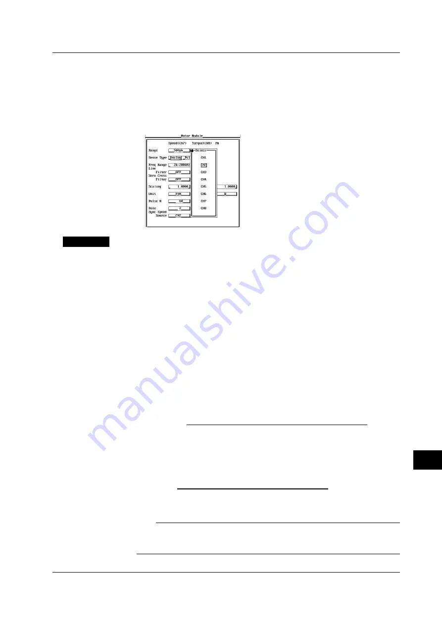
Turn the jog shuttle to select [Sync Speed Source].
4.
Press the SELECT key to display the frequency measurement source setting
box.
5.
Turn the jog shuttle to select the channel from [CH1] to [CH8].
6.
Press the SELECT key to confirm the new frequency measurement source.
Explanation
Setting the motor’s number of poles
Select the value in the range from 1 to 99. This sets the number of poles for the
motor being measured.
Setting the frequency measurement source
Select from the following list of choices:
• CH1 to CH6
Normally, set the input channel for the voltage or current supplied by the motor. If
a frequency other than that of the voltage and current supplied by the motor is
specified, the synchronous speed may not be determined correctly.
• CH7 or CH8
Normally, the rotating speed and torque signals are input to CH7 and CH8. You
can select the signal input to these channels as the frequency measurement
source, but the synchronous speed will not be determined correctly.
Equation for deriving the synchronous speed
The equation when the unit of synchronous speed (Sync) is rpms is indicated below.
120
×
Frequency of the frequency measurement source (Hz)
Motor’s number of poles
Sync (rpm) =
Equation for deriving the slip
The equation when the unit of rotating speed or synchronous speed is rpms is
indicated below.
×
100
Synchronous speed (rpm) – Rotating speed
*
(rmp)
Synchronous speed (rpm)
Slip (%) =
* Rotating speed derived in section 15.4.
Note
Please select a stable voltage or current (supplied by the motor) with small distortion or noise
for the frequency measurement source. Set the zero crossing filter (see section 5.6) as
necessary.
15.6 Setting the Motor’s Number of Poles Used to Compute the Synchronous Speed and the Slip


