5-25
IM 253710-01E
Setting the Measurement Mode and Range
5
5.6
Selecting the Input Filter
«For a functional description, see section 1.3.»
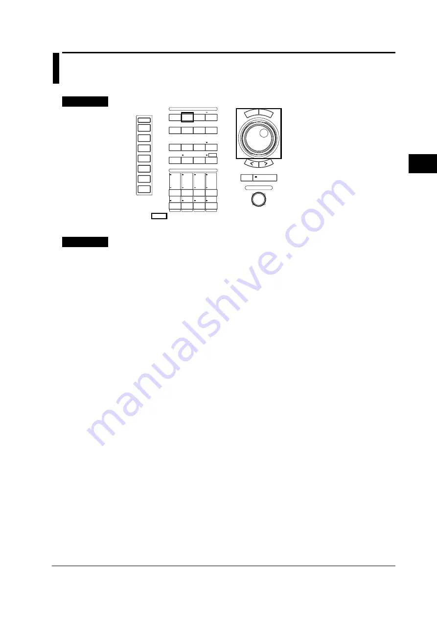
Keys
• The
mark indicates the keys that are used for the operation.
• To exit the menu during operation, press the ESC key.
CONFIGURATION
ELEMENTS
VOLTAGE
CURRENT
FILTER
1
FILTER
FILTER
FILTER
2
3
4
RES
ET SELECT
CH
8
CH
6
CH
4
CH
2
CH
7
CH
5
CH
3
CH
1
OBSERVATION TIME
TRIG’ D
ACQ
REMOTE
MENU
SHIFT
NULL
CAL
COPY
LOCAL
HELP
MISC
FILE
ZOOM
CURSOR
MATH
DISPLAY
SETUP INPUT MEASURE TRIGGER
ABORT
E S C
SINGLE
START
START/STOP
Procedure
Selecting the Input Filter for Each Element
Selects the input filter of the power measurement module for each element.
1.
Press the INPUT key to display the Input setting menu.
On products (PZ4000) with firmware version before 2.01, only the [Power Module] soft
key appears.
2.
Press the [Power Module (Each)] soft key to display the power module setting
dialog box.
The menu does not appear for elements without modules. If the sensor input module is
installed in the element number 4 slot, the menu for element 4 does not appear.
Selecting the line filter
3.
Turn the jog shuttle to select the [Line Filter] of the element you wish to set.
4.
Press the SELECT key to display the line filter selection box.
5.
Turn the jog shuttle to select the filter from [OFF] to [500Hz].
6.
Press the SELECT key to confirm the line filter. The FILTER indicator in the
ELEMENT group on the front panel lights.
Selecting the zero crossing filter
3.
Turn the jog shuttle to select the [Zero Crossing Filter] of the element you wish
to set.
4.
Press the SELECT key to display the zero crossing filter selection box.
5.
Turn the jog shuttle to select the filter from [OFF] to [500Hz].
6.
Press the SELECT key to confirm the zero crossing filter.


