


SmartPad LCD
™
Page:
15
© 2008 Xantech Corporation
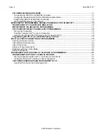
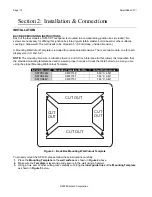
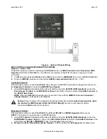
WALL
CUT-OUT WALL TEMPLATE
CUTTING TOOL
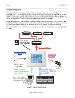
Figure 5 – Cutting the Mounting Hole
4.
After the four areas are cut out, remove the
Mounting Template
and carefully remove the four areas that
remain attached. Clean the area of any loose pieces.
Do not to enlarge the hole past the recommended
dimensions.
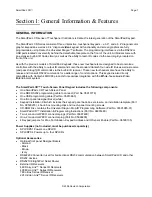
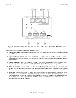
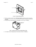
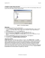
5.
Remove the appropriate
hole-knockouts
on the
Back Box
to allow for wiring of the
SPLCD
.
Cable Access
Punch-Outs
Figure 6 – Back Box Cable Access Point (Back-Box Rear View)
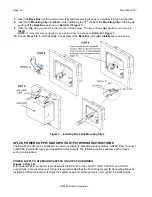
6.
Pull all
cables
through the
wall opening
and desired
punch-out hole
in the
Back Box
.