


Page: 14
SmartPad LCD
™
© 2008 Xantech Corporation
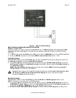
Section 2: Installation & Connections
INSTALLATION
BACK BOX MOUNTING INSTRUCTIONS
Each of the four models of SPLCD Touchpanel is mounted in a corresponding junction box (included). No
screws are necessary for affixing this junction box into drywall, lath & plaster, button board or other surfaces
covering a hollow wall. The wall needs to be at least 3.5” (8.9cm) deep, (inside dimension).
A Mounting Wall-Cutout Template is included for precise hole dimensions. There are two models, one for each
display size (3.9” and 6.4”).
NOTE:
The mounting hole size is critical as there is a +0.00” inch tolerance for this cutout. It is imperative that
the provided mounting template be used to assure proper hole size. Check the table below to be sure you are
using the proper Mounting Wall-Cutout Template.
SPLCD Model #
Mounting Template Part No.
Cutout Dimensions
SPLCD39G
08187158
5.50” X 6.50”
SPLCD64G
08187157
7.63” X 9.49”
SPLCD64V
08187157
7.63” X 9.49”
CUT OUT
CUT OUT
CUT
OUT
CUT
OUT
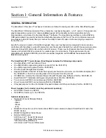
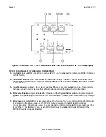
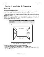
Figure 4 – Back Box Mounting Wall-Cutout Template
To properly mount the SPLCD, please follow these instructions carefully:
1.
Place the
Mounting Template
on the
wall surface
as shown in
Figure 4
above.
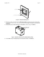
2.
Make sure the
Template
is
level
and gently secure to the wall using a hammer.
3.
Using a hole saw or other cutting tool, carefully cut along the
inner guide lines
of the
Mounting Template
as shown in
Figure 5
below.