


Watlow EZ-ZONE
®
RMC Module
•
205
•
Chapter 7 Features
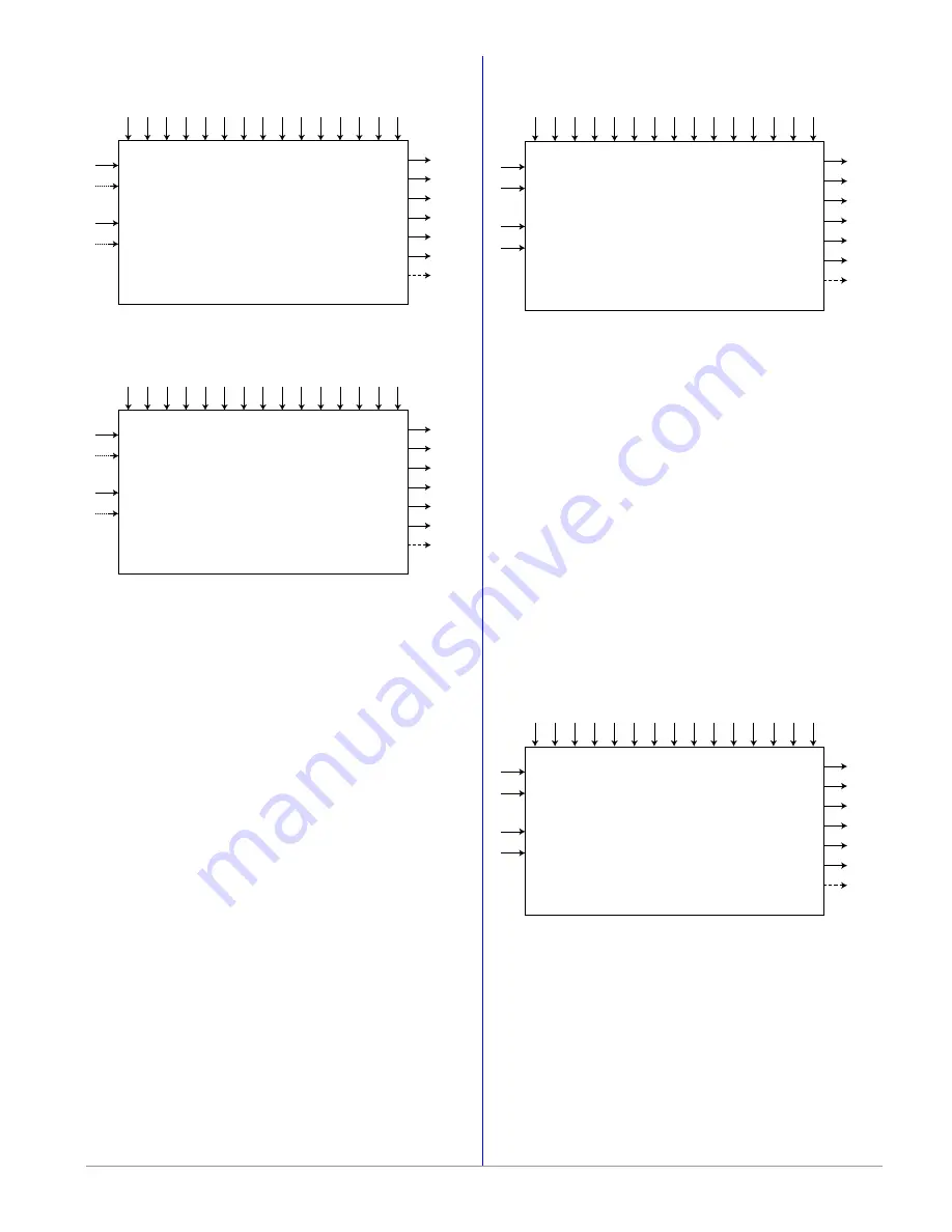
Special Output
Off
Source Function A
Source Instance A
Source Zone A
Source Error A
Source Function B
Source Instance B
Source Zone B
Source Error B
Power On Level 1
Power On Level 2
Power Off Level 1
Power Off Level 2
Minimum On
Time
Minimum Off
Time
Valve
Tra
vel
Time
Dead Band
Output 1 Size
Output 2 Size
Output 3 Size
Output 4 Size
Time Dela
y
Output Order
Function
Output Value 4
Output Value 3
Output Value 2
Output Value 1
Error 1 to 4
Source Value A
Source Value B
Special Output
Compressor
Source Function A
Source Instance A
Source Zone A
Source Error A
Source Function B
Source Instance B
Source Zone B
Source Error B
Power On Level 1
Power On Level 2
Power Off Level 1
Power Off Level 2
Minimum On
Time
Minimum Off
Time
Valve
Tra
vel
Time
Dead Band
Output 1 Size
Output 2 Size
Output 3 Size
Output 4 Size
Time Dela
y
Output Order
Function
Output Value 4
Output Value 3
Output Value 2
Output Value 1
Error 1 to 4
Source Value A
Source Value B
Note:
Typical use scenario for compressor control
is for cooling and/or dehumidification. The
application may have one or two loops of control
which utilize the compressor to accomplish the
cooling and/or dehumidificaition (negative power
levels). Because the compressor is a mechanical
device, it is desirable to minimize starts and stops.
Either loop can attempt to start or stop the
compressor, but this algorithm will make the
determination when it should or should not run.
Because you may not turn the compressor off
until the loop is in the heat or humidify region, the
input values to the compressor algorithm must be
loop power (+/- 100%).
Special Output
Motorized Valve
Source Function A
Source Instance A
Source Zone A
Source Error A
Source Function A
Source Instance A
Source Zone A
Source Error A
Source Function B
Source Instance B
Source Zone B
Source Error B
Source Function B
Source Instance B
Source Zone B
Source Error B
Power On Level 1
Power On Level 1
Power On Level 2
Power On Level 2
Power Off Level 1
Power Off Level 1
Power Off Level 2
Power Off Level 2
Minimum On
Time
Minimum On
Time
Minimum Off
Time
Minimum Off
Time
Valve
Tra
vel
Time
Valve
Tra
vel
Time
Dead Band
Dead Band
Output 1 Size
Output 1 Size
Output 2 Size
Output 2 Size
Output 3 Size
Output 3 Size
Output 4 Size
Output 4 Size
Time Dela
y
Time Dela
y
Output Order
Output Order
Function
Function
Output Value 4
Output Value 4
Output Value 3
Output Value 3
Output Value 2
Output Value 2
Output Value 1
Output Value 1
Error 1 to 4
Source Value A
Source Value A
Source Value B
Source Value B
Special Output
Sequencer
Error 1 to 4
Current Position is an approximation of the valve's
position as it relates to a power level (0 - 100%)
where 0% is fully closed and 100% is fully open.
Dead Time is the minimum on time that the valve
will travel once it is turned on in either the closed
or open direction. Dead Time = Valve Dead Band
/ 100 * Valve Travel Time. On Time is the amount
of time the valve needs to be turned on (either open
or close) to eliminate the error between the
estimated valve position and the desired power
level. A positive On Time value indicates the need
to open the valve while a negative value indicates
the need to close the valve. On Time = (Source A
Value - Current Position) / 100 * Valve Travel Time.
When power is applied to the controller, the valve
is closed and time is set to 0. Output Value 1 is the
close signal to the valve. Output Value 2 is the
open signal to the valve.
A sequencer takes a single input power signal and
splits it up into multiple output signals. Each output
represents a portion of the total output capacity.
The primary output which is often referred to as the
vernier output represents a larger portion of the
total output capacity than any of the other outputs.
The vernier output is always a proportional signal
while the other outputs are ON/OFF.


