


Watlow EZ-ZONE
®
RMC Module
•
6
•
Chapter 1 Overview
A Conceptual View of the RMC Module
The flexibility of the RMC software and hardware al-
lows a large range of configurations. Acquiring a bet-
ter understanding of the controller’s overall function-
ality and capabilities while at the same time plan-
ning out how the controller can be used will deliver
maximum effectiveness in your application.
The RMC can be connected at the system level to
as many as 17 modules, one of which can be an Ac-
cess module and the others (16 maximum) can be any
combination of available modules. The user will de-
fine each address via the button on the face of each
module. Each installed RMC module must have a
unique Standard Bus address ranging from 1-9, A-F,
where the factory defaults for each is Standard Bus
address 1.
Getting Started Quickly
The RMC (Controller) can be ordered with up to
four PID loops with default loop configurations (all
loops) out of the box as follows:
• Analog Input functions set to thermocouple, type
J
• Control loops 1-4 use Analog Inputs 1-4
• Heat algorithm set for PID, Cool set to off
• Outputs set to off
• Control mode set to Auto
• Set point set to 75 °F
To enable a loop for heat simply follow the steps be-
low:
1. Navigate to the Setup Page
2. Once on the Setup Page navigate to the Output
Menu and then the output of choice
3. Change the default setting of Off to Heat Power
4. Select the desired loop instance
EZ-ZONE RMC Default Configuration
Heat
Thermocouple Type J
Analog Input 1
PID
Controller
Heat
Slot A
Loop 1
Input Sensor
Output
Function
Input
Function
Output 1
Off
Note:
Zones can communicate with one another over the
backplane (local and split rail). Once the system is
configured and running, changing zone addresses
without careful deliberation may cause disruption in
operation.
Some of the user selectable ordering options are
listed below:
1. Class 2 or SELV (Saftey Extra Low Voltage) equiv-
alent Power Supplies:
• 90-264 Vac to 24Vdc @ 31 watts
• 90-264 Vac to 24Vdc @ 60 watts
• 90-264 Vac to 24Vdc @ 91 watts
2. RMC Module can provide:
• 1 to 4 control loops, limits or CT inputs
• 1 to 9 inputs (various types)
• 1 to 12 outputs (various types)
• Modbus RTU communications
As can be seen above the RMC module is fully scal-
able with regards to power requirements, number of
loops, inputs, and outputs.
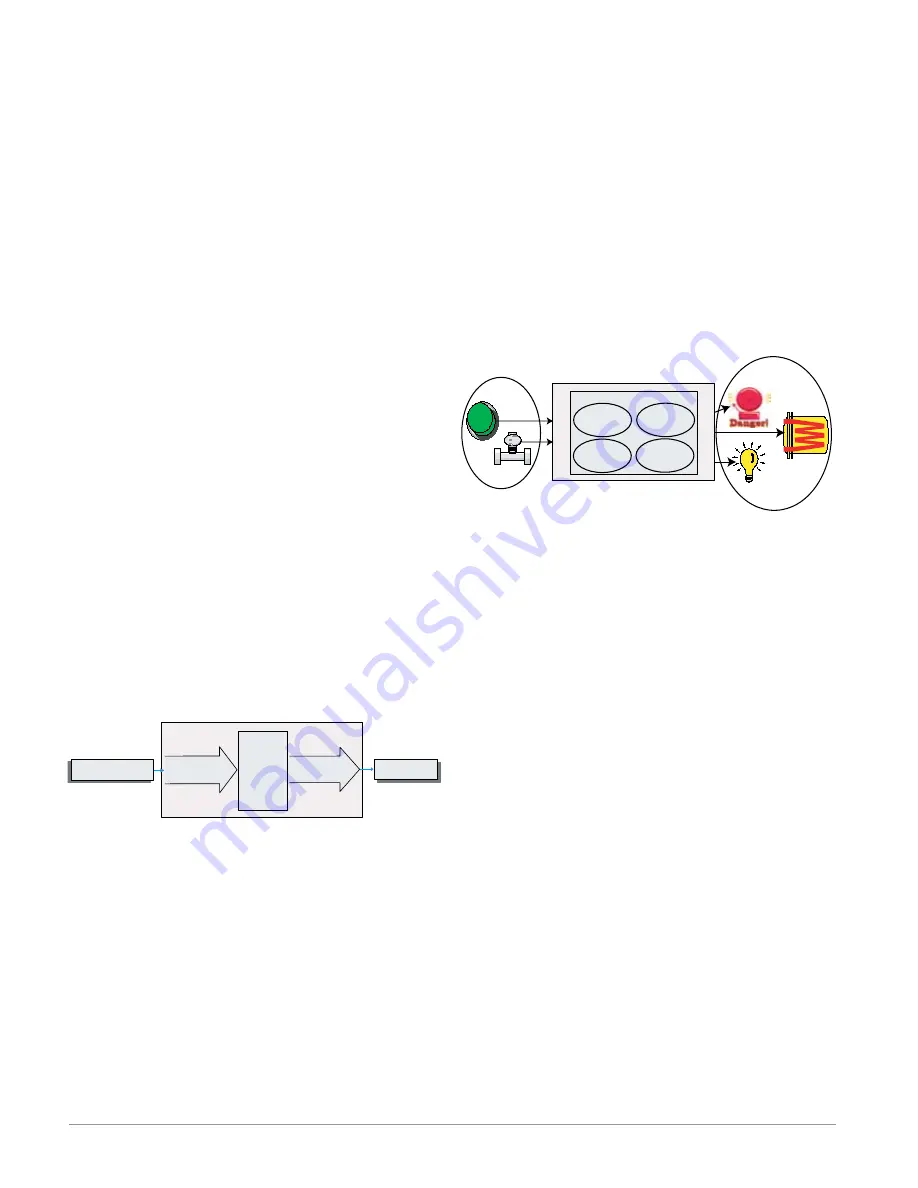
It is useful to think of the controller in three
parts: inputs, functions and outputs. Information
flows from an input to a function to an output when
the controller is properly configured. An RMC mod-
ule can carry out several functions at the same time,
e.g., PID control, monitoring for several different
alarm situations, monitoring and acting upon Digi-
tal Inputs and driving output devices such as heat-
ers, audible alarms, lights. Each process needs to
be thought out carefully and the controller’s inputs,
functions and outputs set up properly.
Functions
Outputs
Process
Alarm
High
PID
Heat
Power
Sequencing
Outputs
Silence
Alarms
Inputs
Functions
Functions use input signals to calculate a value. A
function may be as simple as reading a digital input
to set a state to true or false, or reading a tempera-
ture to set an alarm state to on or off. Alternatively,
if a failure with the primary sensing device should
occur, sensor backup could be utilized to avoid an un-
wanted shutdown.
To set up a function, one of the first things that
must be considered is the function source and in-
stance. For example, if the control is equipped with
Digital Inputs (source) and it was decided to use DI 9
(instance) it can then be associated with an Action to
reset an individual alarm or all alarms. To configure
as such, follow the steps below:
Setup Page (Digital I/O Menu)
1. Navigate to the Setup Page and then to the Digital
I/O menu.
2. Select the desired instance and set the direction to
input voltage or input dry contact.
Setup Page (Action Menu)
3. Navigate to the Setup Page and then the Action
menu.
4. Set the Action Function to Alarm
5. Select which alarm instance will be reset (0 equals
all)
6. Select the Source Function to Digital I/O
7. Select the Source Instance (step 2 above)
8. Select the Source Zone (0 equals the module being
configured).
9. Select the Active Level to execute the desired func-
tion.


