SK00-4390-DI-002-11
35
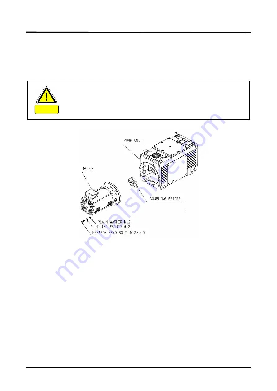
(5) Put the new coupling spider in one of the coupling. Meet the ratchet of both couplings and
mount the pump unit in the medium case.
(6) Put the M12 hexagon head bolt x 4 and spring washer x 4 and plain washer x 4 removed
in the item (2) above (Recommended tightening torque: 45N
・
m).
(7) Execute the wiring.
CAUTION
Use the loading equipment such as a crane to put on and take out the
Motor to ensure the safety. Be sure to turn OFF the Power Supply when
putting on and taking out the Motor.
Only the technically entitled person should be in charge of operating the
machine such as crane.
Fig. 10 Replacement of coupling spider
6.2.9 Checking The Oil Mist Trap
To use the Oil mist trap, be cautious not to have clog of the filter in the trap. Too much clog
would prevent the exhaust gas from passing through the filter, raise the pressure inside the
Pump unit and might result in breaking it.
Limit value of the pressure inside the Pump is 0.03MPaG (0.3kg/cm
2
G) (Gauge pressure). We
recommend you to install a Pressure monitor. Refer to the Instruction Manual of the Oil mist
trap as for the install position of the Pressure monitor.
It is recommended to mount a pressure monitor (G1/4). For the pressure monitor mounting
position, refer to the instruction manual for the oil mist trap.
Содержание VS1501
Страница 2: ......
Страница 13: ...SK00 4390 DI 002 11 xi Fig 1 Warning Label display position...
Страница 27: ...SK00 4390 DI 002 11 7 Fig 2 VS1501 Dimensional drawing...
Страница 28: ...SK00 4390 DI 002 11 8 Fig 3 VS2401 Dimensional drawing...
Страница 36: ...SK00 4390 DI 002 11 16 Fig 5 Suction Exhaust piping connection diagram...


