7
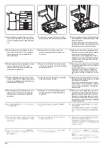
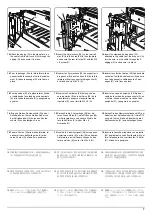
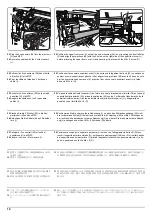
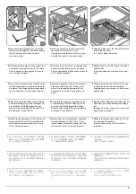
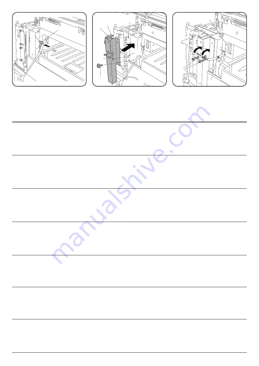
14.
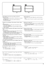
Attach the edging (D) to the side plate, run
the cable from the drive unit (A) through the
edging (D) and secure it in place.
15.
Insert the 2 projections (28) on the rear left
stay (E) into the holes (29) in the side plate
and secure the rear left stay (E) with the M4
× 8 screw (O).
16.
Insert the clamped binding band (30)
attached to the cable from the drive unit (A)
into the hole, run the cable through the 2
edgings (31) and secure it in place.
14.
Fixer le passage (D) à la tôle latérale, faire
passer le câble venant de l'unité d'entraîne-
ment (A) dans le passage (D) et le fixer en
place.
15.
Insérer les 2 projections (28) du support arri-
ère gauche (E) dans les trous (29) de la tôle
latérale et fixer le support arrière gauche (E)
à l'aide d'une vis M4 × 8 (O).
16.
Insérer le collier de fixation (30) fixé au câble
venant de l'unité d'entraînement (A) dans le
trou, faire passer le câble dans les 2 pas-
sages (31) et le fixer en place.
14.
Fije la pestaña (D) a la placa lateral, tienda
el cable desde la unidad de accionamiento
(A) a través de la pestaña (D) y asegúrelo en
posición.
15.
Inserte los 2 salientes (28) del soporte tra-
sero izquierdo (E) en los orificios (29) de la
placa lateral y asegure el soporte trasero
izquierdo (E) con el tornillo M4 × 8 (O).
16.
Inserte la correa de sujeción (30) fijada al
cable de la unidad de accionamiento (A) en
el orificio, tienda el cable a través de las 2
pestañas (31) y asegúrelo en posición.
14.
Bringen Sie den Kantenschutz (D) an der
Seitenplatte an, führen Sie das Kabel von
der Antriebseinheit (A) durch den Kanten-
schutz (D) und befestigen Sie es.
15.
Setzen Sie die 2 Vorsprünge (28) der hin-
teren linken Stütze (E) in die Öffnungen (29)
der Seitenplatte ein und sichern Sie die hin-
tere linke Stütze (E) mit der M4 × 8
Schraube (O).
16.
Setzen Sie das Klemmschellenband (30) am
Kabel von der Antriebseinheit (A) in die Öff-
nung ein, führen Sie das Kabel durch die 2
Kantenschutze (31) und befestigen Sie es.
14.
Fissare il bordo (D) alla piastra laterale, far
passare il cavo dall'unità guida (A) attra-
verso il bordo (D) e fissarlo in posizione.
15.
Inserire le 2 parti sporgenti (28) sul supporto
posteriore sinistro (E) nei fori (29) nella pias-
tra laterale, e quindi fissare il supporto pos-
teriore sinistro (E) con la vite M4 × 8 (O).
16.
Inserire la fascetta di legatura con morsetto
(30) applicata al cavo dell'unità guida (A) nel
foro, far passare il cavo attraverso i 2 bordi
(31) e fissarlo in posizione.
14.
側板にエッジング (D) を取り付け、駆動ユ
ニット (A) からの電線を通し、固定する。
15.
左後ステー(E) の 2 個の突起 (28) を側板の
穴 (29) に入れて、ビス M4×8(O)1 本で左後
ステー(E) を固定する。
16.
駆動ユニット (A) からの電線に付いている
クランプ付き結束バンド (30) を穴に入れ固
定し、
2 箇所のエッジング (31) に通し、固定
する。
14.
在侧板上安装电线护具 (D),将来自驱动单元
(A) 的电线从其中穿过以进行固定。
15.
将左后部支架 (E) 的 2 处突出部 (28) 插入侧
板的孔 (29) 中,使用 1 颗 M4×8 螺丝 (O) 来
固定左后部支架 (E)。
16.
将来自驱动单元 (A) 的电线附带的带夹头束
线带 (30) 插入孔中固定,并使其从 2 处电线
护具 (31) 中通过以固定。
14.
측면판에 에징 (D) 을 부착 , 구동 유니트 (A)
의 전선을 통과시키고 고정합니다 .
15.
좌측 뒷 받침대 (E) 의 돌기 (28) 2 개를 측면
판의 구멍 (29) 에 넣고 나사 M4×8(O)1 개로
좌측 뒷 받침대 (E) 를 고정합니다 .
16.
구동 유니트 (A) 의 전선에 붙어 있는 클램프
부착 결속밴드 (30) 를 구멍에 넣고 고정해 2
곳의 에징 (31) 을 통과 시켜 고정합니다 .
A
D
E
28
29
28
O
29
A
31
30
Содержание UTAX AK 730
Страница 5: ...This page is intentionally left blank ...
Страница 11: ...This page is intentionally left blank ...
Страница 15: ...3NB 3ND 3N0 3NK This page is intentionally left blank ...
Страница 25: ...3NB 3ND 3N0 3NK 1 1 10 This page is intentionally left blank ...
Страница 43: ...3NB 3ND 3N0 3NK 1 2 18 3 Remove tape and pad Figure 1 2 23 Tape Pad ...
Страница 45: ...3NB 3ND 3N0 3NK 1 2 20 This page is intentionally left blank ...
Страница 81: ...3NB 3ND 3N0 3NK 1 3 36 This page is intentionally left blank ...
Страница 157: ...3NB 3ND 3N0 3NK 1 4 76 This page is intentionally left blank ...
Страница 169: ...3NB 3ND 3N0 3NK 1 5 12 This page is intentionally left blank ...
Страница 206: ...3NB 3ND 3N0 3NK 2 2 11 This page is intentionally left blank ...
Страница 246: ...1 1 INSTALLATION GUIDE INSTALLATION GUIDE FOR 4000 SHEETS FINISHER ...
Страница 269: ...INSTALLATION GUIDE FOR FINISHER ATTACHMENT KIT MFP A ...
Страница 283: ...INSTALLATION GUIDE FOR FINISHER ATTACHMENT KIT MFP B ...
Страница 284: ...E F A H G I J B D C ...
Страница 291: ...INSTALLATION GUIDE FOR FINISHER ATTACHMENT KIT PRINTER ...
Страница 295: ...INSTALLATION GUIDE FOR CENTER FOLDING UNIT ...
Страница 312: ...INSTALLATION GUIDE FOR MULTI TRAY ...
Страница 326: ...INSTALLATION GUIDE FOR MULTI TRAY ATTACHMENT KIT PRINTER ...
Страница 330: ...INSTALLATION GUIDE FOR PUNCH UNIT ...


