background image

3NB/3ND/3N0/3NK

2-2-9

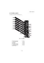
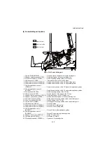
(7) Mailbox (option)

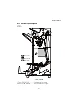
Figure 2-2-9 Mailbox

1. Mailbox main PWB (MBMPWB)............ Controls electric components of mailbox.
2. Tray overflow switch 1 (TOFSW1) ........ Detected overflow of ejected to tray 1.
3. Tray overflow switch 2 (TOFSW2) ........ Detected overflow of ejected to tray 2.
4. Tray overflow switch 3 (TOFSW3) ........ Detected overflow of ejected to tray 3.
5. Tray overflow switch 4 (TOFSW4) ........ Detected overflow of ejected to tray 4.
6. Tray overflow switch 5 (TOFSW5) ........ Detected overflow of ejected to tray 5.
7. Tray overflow switch 6 (TOFSW6) ........ Detected overflow of ejected to tray 6.
8. Tray overflow switch 7 (TOFSW7) ........ Detected overflow of ejected to tray 7.
9. Tray eject sensor (TEJS) ...................... Detection of paper jam.

10. Tray eject sensor (TEJS) ...................... Radiates the pulse of LED.

11. MB home position switch (MHPSW) ..... Controls mailbox drive motor.

12. MB cover open/close switch

( MCOSW)............................................... Detects the mailbox cover is open.

13. MB drive motor (MBDM) ....................... Drives paper conveying section of mailbox.
14. MB feedshift solenoid (MBSOL)............ Operates the feedshift guide.

1

2

3

4

5

6

7

8

9

10

13

11

12

14

Machine front

Machine inside

Machine rear

Содержание UTAX AK 730

Страница 1: ...Service Manual Document Finisher DF 790 B C Booklet Folder BF 730 Multi Tray MT 730 B Attachment Kit AK 730 731 735 Punch Unit PH 7 Rev 3 0 Date 27 05 2015 3NBSM063 ...

Страница 2: ...Service Manual Document Finisher DF 790 B C Booklet Folder BF 730 Multi Tray MT 730 B Attachment Kit AK 730 731 735 Punch Unit PH 7 Rev 3 0 Date 27 05 2015 3NBSM063 ...

Страница 3: ...E EST REMPLACEE PAR UN MODELE DE TYPE INCORRECT METTRE AU REBUT LES BATTERIES UTILISEES SELON LES INSTRUCTIONS DONNEES Il peut être illégal de jeter les batteries dans des eaux d égout municipales Vérifiez avec les fonctionnaires municipaux de votre région pour les détails concernant des déchets solides et une mise au rebut appropriée The MFPs mentioned in the service manual are of the following c...

Страница 4: ... 1 4 24 1 4 26 1 4 27 2 1 1 2 1 13 2 2 6 2 3 17 2 3 18 2 4 1 to 2 4 8 2 March 29 2013 Cover Contents 1 1 1 1 1 2 1 1 4 to 1 1 9 1 2 3 to 1 2 5 1 2 13 1 2 15 1 2 16 1 3 1 to 1 3 4 1 3 8 to 1 3 10 1 3 19 to 1 3 35 1 4 1 to 1 4 67 1 4 71 1 4 73 1 4 75 1 5 6 to 1 5 8 2 1 1 to 2 1 3 2 1 10 2 1 11 2 1 20 2 2 6 2 2 7 2 3 6 2 3 16 to 2 3 21 2 4 1 2 4 9 to 2 4 15 3 May 15 2015 Contents 1 5 9 to 1 5 11 ...

Страница 5: ...This page is intentionally left blank ...

Страница 6: ...rsonnel to ensure the safety of their customers their machines as well as themselves during maintenance activities Service personnel are advised to read this booklet carefully to familiarize themselves with the warnings and precautions described here before engaging in maintenance activities ...

Страница 7: ... this symbol CAUTION Bodily injury or damage to property may result from insufficient attention to or incorrect com pliance with warning messages using this symbol Symbols The triangle symbol indicates a warning including danger and caution The specific point of attention is shown inside the symbol General warning Warning of risk of electric shock Warning of high temperature indicates a prohibited...

Страница 8: ...d or dusty place This may cause fire or electric shock Do not install the copier near a radiator heater other heat source or near flammable material This may cause fire Allow sufficient space around the copier to allow the ventilation grills to keep the machine as cool as possible Insufficient ventilation may cause heat buildup and poor copying performance Always handle the machine by the correct ...

Страница 9: ... carefully Always check that the copier is correctly connected to an outlet with a ground connection Check that the power cable covering is free of damage Check that the power plug is dust free If it is dirty clean it to remove the risk of fire or electric shock Never attempt to disassemble the optical unit in machines using lasers Leaking laser light may damage eyesight Handle the charger section...

Страница 10: ... caution labels that should be present on the machine according to the instruction handbook are clean and not peeling Replace with new ones if necessary Handle greases and solvents with care by following the instructions below Use only a small amount of solvent at a time being careful not to spill Wipe spills off completely Ventilate the room well while using grease or solvents Allow applied solve...

Страница 11: ...This page is intentionally left blank ...

Страница 12: ...2 Paper misfeed detection condition MFP 1 4 3 1 4 3 Paper misfeed detection condition Full color Printer 1 4 11 1 4 4 Troubleshooting 1 4 19 1 First check items 1 4 19 2 Items and corrective actions relating to the device that will cause paper jam 1 4 24 3 Electrical parts that could cause paper jam at the BR bridge part 1 4 32 4 Electrical parts that could cause paper jam at the DF paper entry fe...

Страница 13: ...ion 2 1 12 1 Main tray elevation operation 2 1 14 2 Collation 2 1 14 2 1 5 Center folding unit section option 2 1 15 1 Paper centerfold operation center folding tri folding 2 1 17 2 1 6 Mailbox option 2 1 20 1 Eject operation to mailbox tray 2 1 22 2 1 7 Punch unit Option 2 1 23 2 2 Electrical Parts Layout 2 2 1 Electrical parts layout 2 2 1 1 PWBs 2 2 1 2 Switches and sensors 2 2 2 3 Motors 2 2 4...

Страница 14: ...N0 3NK 2 INSTALLATION GUIDE 4000 SHEETS FINISHER FINISHER ATTACHMENT KIT MFP A FINISHER ATTACHMENT KIT MFP B FINISHER ATTACHMENT KIT PRINTER CENTER FOLDING UNIT MAILBOX MAILBOX ATTACHMENT KIT PRINTER PUNCH UNIT ...

Страница 15: ...3NB 3ND 3N0 3NK This page is intentionally left blank ...

Страница 16: ...g Maximum Number A3 B4 B5R Ledger Legal Oficio II 12 18 216 340 mm Folio 8K 16KR 30 sheets 52 to 90 g m2 20 sheets 91 to 105 g m2 2 cover sheet only 106 g m2 to 135 g m2 A4 A4R B5 Letter Letter R 16K 70 sheets 52 to 74 g m2 65 sheets 75 to 90 g m2 55 sheets 91 to 105 g m2 2 cover sheet only 106 g m2 to 135 g m2 Media types Plain Recycled Prepunched Preprinted Bond Letterhead Color Colour Vellum Th...

Страница 17: ... Fold A3 B4 A4R Ledger Legal Letter R Oficio II 8K Saddle Stitch A3 B4 A4R Ledger Legal Letter R Oficio II 8K Tri Fold A4R Letter R Number of sheets Bi Fold 5 sheets 60 to 90 g m2 3 sheets 91 to 120 g m2 1 sheet 121 to 256 g m2 Saddle Stitch 16 sheets 60 to 90 g m2 13 sheets 91 to 105 g m2 1 cover sheet only 106 to 256 g m2 Tri Fold 5 sheets 60 to 90 g m2 3 sheets 91 to 120 g m2 Maximum number for...

Страница 18: ...3NK 1 1 3 1 1 2 Parts names 1 Document Finisher Figure 1 1 1 5 4 2 1 3 6 1 DF Main tray tray A 2 DF left sub tray tray B 3 DF right sub tray tray C 4 DF upper front cover 5 DF lower front cover 6 DF operation panel ...

Страница 19: ... Centerfold unit option 1 Centerfold unit release lever 2 Centerfold tray 3 Centerfold unit top cover 4 Staple cartridge holder 5 Staple cartridge holder 6 Centerfold bridge unit Mailbox option 7 Trays 1 7 8 Mailbox cover The mailbox can be installed either the main unit or the 4000 sheet fin isher Not installable at the same time ...

Страница 20: ...3NB 3ND 3N0 3NK 2 1 1 5 3 Bridge unit For installing with MFP A Figure 1 1 3 2 1 4 3 5 1 BR eject cover 2 BR conveying unit 3 BR conveying cover 4 BR drive unit 5 BR entry unit ...

Страница 21: ...ND 3N0 3NK 2 1 1 6 4 Bridge unit For installing with MFP B Figure 1 1 4 2 1 5 3 6 4 1 BR eject cover 2 BR conveying unit 3 BR conveying cover 4 BR conveying cover open lever 5 BR drive unit 6 BR entry guide ...

Страница 22: ...3NB 3ND 3N0 3NK 2 1 1 7 5 Bridge unit For installing with full color printers Figure 1 1 5 1 2 1 BR conveying cover 2 BR cover open lever ...

Страница 23: ...re 1 1 6 Paper path 8 1 6 10 4 2 3 5 7 9 1 DF processing section 2 Right sub tray eject section 3 Left sub tray eject section 4 Main tray eject section 5 Staple unit 6 Bridge unit section 7 Center folding bridge unit 8 Center folding unit option 9 Mailbox option 10 Punch unit Option ...

Страница 24: ...he 4000 sheet finisher Not installable at the same time 9 8 1 6 10 4 2 3 5 7 9 Paper path 1 DF processing section 2 Right sub tray eject section 3 Left sub tray eject section 4 Main tray eject section 5 Staple unit 6 Bridge unit section 7 Center folding bridge unit 8 Center folding unit option 9 Mailbox option 10 Punch unit Option ...

Страница 25: ...3NB 3ND 3N0 3NK 1 1 10 This page is intentionally left blank ...

Страница 26: ... high humidity or low temperature and low humidity an abrupt change in the environmental temperature and cool or hot direct air Avoid places subject to dust and vibrations Choose a surface capable of supporting the weight of the machine Place the machine on a level surface maximum allowance inclination 1 Avoid air borne substances that may adversely affect the machine or degrade the photoconductor...

Страница 27: ...0 1 Skid 2 Bottom right pad 3 Bottom left pad 4 Document Finisher 5 Plastic sheet 6 Outer case 7 Upper right pad 8 Upper left pad 9 Spacer A 10 Finisher tray 11 Spacer B 12 Earth connection plate 13 Earth spring 14 Wire guide 15 Staple cartridge 16 Eject guide 17 M4 x 8 screw 18 M4 x 10 screw black 19 M4 x 30 screw 20 Upper earth plate 21 Connecting plate 22 Installation guide etc 23 Hinge joints ...

Страница 28: ...m spacer 3 Bridge conveying unit 4 Bridge entry unit 5 Bridge drive unit 6 Bridge eject unit 7 Spacer A 8 Spacer B 9 Top spacer 10 Left connevtion cover 11 Upper front cover 12 Left scanner cover 13 Lower connevtion cover 14 Left cover 15 Front left stay 16 Rear left stay 17 Upper left cover 18 Edging 19 Wire stopper 20 M4 x 8 screw 21 M4 x 20 screw 22 P Tite screw M3 x 8 23 Installation guide etc...

Страница 29: ...17 18 13 1 3 6 4 2 5 7 12 8 19 1 Outer case 2 Bottom spacer 3 Side spacer 4 Tray A 5 Bridge unit 6 Cover sheets 7 Tray B 8 Left front cover 9 Front upper cover 10 ISU left cover 11 Guide rail 12 Tray C 13 Left cover 14 Rear left upper cover 15 Front left lower stay 16 Rear left stay 17 Front left stay 18 Tray D 19 Installation guide etc ...

Страница 30: ...Printer Figure 1 2 4 See the Installation Guide for installation 3 6 5 4 7 8 9 10 11 12 1 2 1 Outer case 2 Bottom spacer 3 Bridge unit 4 Spacer A 5 Spacer B 6 Top spacer 7 M4 x 8 screw 8 Pin 9 Cover 10 Earth Plate 11 Cover 12 Installation guide etc ...

Страница 31: ...3NB 3ND 3N0 3NK 1 2 6 Center folding Unit Figure 1 2 5 17 19 11 4 3 13 2 5 15 29 16 8 14 6 7 18 20 12 9 10 1 21 22 23 24 25 26 27 28 ...

Страница 32: ...heet 7 Top spacer 8 Spacer C 9 Center folding bridge unit 10 Spacer D 11 Spacer E 12 CF tray 13 Spacer F 14 Front rail 15 Rear rail 16 Guide 17 Spacer G 18 CF stock tray 19 Spacer H 20 Output stopper 21 Front side cover 22 Rear side cover 23 Pin 24 M4 x 8 screw 25 M4 x 10 screw 26 M4 x 12 screw 27 Lock plate 28 Binding band 29 Installation guide etc ...

Страница 33: ...9 10 12 11 16 17 15 14 13 1 Mailbox 2 Outer case 3 Inner case 4 Bottom pad A 5 Bottom pad B 6 Plastic sheet 7 Inner pad 8 Side spacer 9 Accessory case 10 Trays 11 Plastic bag 12 Plastic bag 13 Front mounting plate cover 14 Rear mounting plate cover 15 M4 x 12 screw 16 Tray name label 17 Installation guide etc ...

Страница 34: ...ter Figure 1 2 7 See the Installation Guide for installation 1 2 6 9 10 5 4 3 8 7 11 1 Outer case 2 Plastic sheet 3 spacer 4 Left cover 5 Plastic sheet 6 Right cover 7 Plastic sheet 8 Solenoid unit 9 Trays 10 Plastic bag 11 M4 x 12 screw 12 Installation guide etc ...

Страница 35: ...N0 3NK 1 2 10 2 Removing the tapes and pads Document Finisher Procedure 1 Remove tape from the finisher try Figure 1 2 8 2 Remove five tapes from the document finisher Figure 1 2 9 Tape Tape Tape Tape Tape Tape ...

Страница 36: ...3NB 3ND 3N0 3NK 1 2 11 3 Open the DF upper front cover Figure 1 2 10 4 Remove three tapes and pad Figure 1 2 11 DF upper front cover Tape Tape Tape Pad ...

Страница 37: ...3NB 3ND 3N0 3NK 1 2 12 5 Remove tape from the DF upper rear cover Figure 1 2 12 6 Remove the lid rear cover and then remove tape Figure 1 2 13 DF Upper rear cover Tape Tape Lid rear cover ...

Страница 38: ...ND 3N0 3NK 2 1 2 13 Bridge unit For installing with MFP A Procedure 1 Remove tape from the bridge entry unit Figure 1 2 14 2 Remove five tapes from bridge convey ing unit Figure 1 2 15 Tape Tapes Tape Tapes ...

Страница 39: ...The protective tape fixing the BR ejec tion cover should be removed before installation holding the BR ejection cover by the hand to prevent it from opening Leaving the BR ejection cover open can cause the internal BR transportation guide to fall Figure 1 2 17 Tape Tape BR conveying guide Pad Pad Tape Tape Tape BR eject cover ...

Страница 40: ... 3NK 2 1 2 15 5 Remove tape from the bridge drive unit Figure 1 2 18 Bridge unit For installing with MFP B Procedure 1 Remove tape from the bridge entry unit Figure 1 2 19 Tape Pad Tape B Tape B Tape A Bridge unit ...

Страница 41: ...3NB 3ND 3N0 3NK 2 1 2 16 Bridge unit Full color Printer Procedure 1 Remove two tapes from the bridge unit Figure 1 2 20 Tape Tape ...

Страница 42: ...emove two tapes and paper Figure 1 2 21 2 Remove nine tapes and pad Note Remove the tapes from the wire guide during installation Refer to the installa tion guide Figure 1 2 22 Tape Tape Paper Pad Tape Tape Tape Tape Tape Tape Tape Tape Tape Wire guide Tape ...

Страница 43: ...3NB 3ND 3N0 3NK 1 2 18 3 Remove tape and pad Figure 1 2 23 Tape Pad ...

Страница 44: ...3NB 3ND 3N0 3NK 1 2 19 Mail box Procedure 1 Remove two tapes Figure 1 2 24 2 Remove five tapes and paper Figure 1 2 25 Tape Tape Tape Tape Tape Tape Tape Paper ...

Страница 45: ...3NB 3ND 3N0 3NK 1 2 20 This page is intentionally left blank ...

Страница 46: ...ng the numeric keys Enter the maintenance item number using the cursor up down keys or numeric keys The selected maintenance item is run Press the stop key Press the start key Start End Maintenance mode is entered The maintenance item is selected Maintenance mode is exited Repeat the same maintenance item Run another maintenance item No No Yes Yes Enter 001 using the cursor up down keys or numeric...

Страница 47: ... Operation panel and support equipment U234 Setting punch destination Inch Inch Europe Met ric Metric U237 Setting finisher stack quantity 0 0 U240 Checking the operation of the finisher U241 Checking the operation of the finisher U246 Setting the finisher Finisher 0 0 0 0 0 0 0 0 Booklet 0 0 0 0 0 0 0 0 0 Others U905 Checking counts by optional devices ...

Страница 48: ...ner Boot Scanner booting RFID RFID ROM IH CPU IH CPU ROM IH CPU Boot IH CPU booting Motor CPU Motor CPU ROM Motor CPU Boot Motor CPU booting Dictionary Option Language Optional language ROM PDF1 7 Resource PDF1 7 resource ROM Solution Framework Framework ROM FMU FMU ROM Weekly Timer Weekly Timer ROM Color Table1 Copy Color table 1 copy ROM Color Table2 Copy Color table 2 copy ROM Color Table1 Prn ...

Страница 49: ...per feeder Side large capacity feeder ROM PF2 Boot Side paper feeder Side large capacity feeder booting DF 4000 sheet finisher ROM DF Boot 4000 sheet finisher booting PH Punch unit ROM PH Boot Punch unit booting MT Mailbox ROM MT Boot Mailbox booting BF Center folding unit ROM BF Boot Center folding unit booting Fax APL1 Fax APL 1 Fax Boot1 Fax booting 1 Fax IPL1 Fax IPL 1 Fax APL2 Fax APL 2 dual ...

Страница 50: ... start key 2 Select the destination Initial setting Inch Inch specifications Europe Metric Metric specifications 3 Press the start key The setting is set 4 Turn the main power switch off and on Allow more than 5 seconds between Off and On Item No Description Display Description Auto Conforms to destination settings Japan Metric Metric Japan specifications Inch Inch North America specifications Eur...

Страница 51: ...Change the setting using the keys or numeric keys Initial setting 0 Number of sheets of stack on the internal tray for non staple copying 10 sheets 2 Press the start key The setting is set 3 Turn the main power switch off and on Allow more than 5 seconds between Off and On Item No Description Display Description Main Tray Number of sheets of stack on the main tray Middle Tray Number of sheets of s...

Страница 52: ...le H DF middle motor DFMM is turned on at high speed Middle L DF middle motor DFMM is turned on at low speed Eject H DF eject motor DFEM is turned on at high speed Eject L DF eject motor DFEM is turned on at low speed Save H DF drum motor DFDRM is turned on at high speed Save L DF drum motor DFDRM is turned on at low speed Tray DF tray motor DFTM is turned on Staple Move DF slide motor DFSLM is tu...

Страница 53: ...y DF feedshift solenoid DFFSSOL is turned on Save Drum DF drum solenoid DFDRSOL is turned on Booklet DF center fold solenoid DFCFSOL is turned on Punch Punch solenoid PUSOL is turned on Three Fold CF feedshift solenoid CFFSSOL is turned on Display Description Conv Mailbox drive motor MBDM is turned on at paper conveying Branch Mailbox drive motor MBDM is turned on at feedshift operation Display De...

Страница 54: ...hecking the switch and sensor of the center folding unit Punch Checking the switch and sensor of the punch unit Display Description Front Cover DF front cover switch DFFCSW MPT DF eject cover switch DFECSW Top Cover DF top cover switch DFTCSW Tray U Limit DF tray upper limit sensor DFTULS Tray HP2 DF tray sensor 2 DFTS2 Tray Middle DF tray middle sensor DFTMS Tray L Limit DF tray upper limit senso...

Страница 55: ...sor 1 DFSFS1 Shift Tail HP DF shift sensor 2 DFSFS2 Shift Unlock HP DF shift release sensor DFSFRS Sub Tray Full DF sub tray full sensor DFSTFS Shift Set DF shift set sensor DFSFSS Display Description Eject MB eject sensor MBES Cover MB cover open close switch MBCOCSW Over Flow1 MB overflow sensor 1 MBOFS1 Over Flow2 MB overflow sensor 2 MBOFS2 Over Flow3 MB overflow sensor 3 MBOFS3 Over Flow4 MB ...

Страница 56: ...CFPES Eject CF eject sensor CFES Paper CF paper sensor CFPS Tray Full CF tray full sensor CFTFS Bundle Up HP CF adjustment sensor 1 CFADS1 Bundle Down HP CF adjustment sensor 2 CFADS2 Width Up HP CF side registration sensor 1 CFSRS1 Width Down HP CF side registration sensor 2 CFSRS2 Blade HP CF blade sensor CFBLS Tray CF tray switch CFTSW Set CF set switch CFSSW Left Guide CF left guide switch CFL...

Страница 57: ...vides optimization when paper jam occurs due to an inferior fitting of the side registration guides to paper Adjustment of booklet stapling position Adjusts the booklet stapling position in the stitching mode if the position is not proper Adjustment of center folding position Adjusts the center folding position in the stitching mode if the position is not proper Adjustment of tri folding position ...

Страница 58: ...g the keys or numeric keys If the distance of the position of a punch hole is smaller than the specified value A increase the setting value If the distance is larger than the value A decrease the setting value Figure 1 3 2 3 Press the start key The value is set Item No Description Description Setting range Initial setting Change in value per step Adjustment of registration stop timing 20 to 20 0 0...

Страница 59: ...peat the above adjustment until paper is properly in position Setting Shift Front HP Shift Tail HP 1 Select Shift Front HP or Shift Tail HP 2 Change the setting value using the keys or numeric keys 3 Press the start key The value is set 4 Press the stop key The screen for selecting a maintenance item No is displayed 5 Enter maintenance mode U240 and select Motor then Sort Test 6 Repeat the above a...

Страница 60: ...p Adjustment of front and back stapling home position 15 to 15 0 0 19 mm Sample 2 Sample 1 Display Description Width Up HP Adjustment of upper side registration home position Width Down HP Adjustment of lower side registration home position Staple Pos1 Adjustment of booklet stapling position for A4 Letter size Staple Pos2 Adjustment of booklet stapling position for B4 Legal size Staple Pos3 Adjust...

Страница 61: ...ple Pos3 2 Change the setting value using the keys or numeric keys When staples are placed too far right sample 1 decrease the preset value When staples are placed too far left sample 2 increase the preset value Reference value within 2 mm Figure 1 3 5 3 Press the start key The value is set Item No Description Description Setting range Initial setting Change in value per step Adjustment of upper s...

Страница 62: ... too far right sample 1 increase the preset value When the tri fold position too far left sample 2 decrease the setting value Reference value A 7 0 2 mm Figure 1 3 7 3 Press the start key The value is set Completion Press the stop key The screen for selecting a maintenance item No is displayed Item No Description Description Setting range Initial setting Change in value per step Adjustment of cent...

Страница 63: ... Display Description DP Counts of DP DF Counts of 4000 sheet finisher Display Description ADP No of single sided originals that has passed through the DP RADP No of double sided originals that has passed through the DP CIS No of dual scan originals that has passed through the DP Display Description Sorter No of copies that has passed Staple Frequency the stapler has been activated Punch Frequency ...

Страница 64: ...the numeric keys Enter the maintenance item number using the cursor up down keys or numeric keys The selected maintenance item is run Press the stop key Press the start key Start End Maintenance mode is entered The maintenance item is selected Maintenance mode is exited Repeat the same maintenance item Run another maintenance item No No Yes Yes Enter 001 using the cursor up down keys or numeric ke...

Страница 65: ...peration panel and support equip ment U234 Setting punch destination Inch Inch Europe Metric Metric U237 Setting finisher stack quantity 0 0 U240 Checking the operation of the finisher U241 Checking the operation of the switches of the finisher U246 Setting the finisher Finisher 0 0 0 0 0 0 0 0 Booklet 0 0 0 0 0 0 0 0 0 Others U905 Checking counts by optional devices ...

Страница 66: ...t IH CPU booting Motor CPU Motor CPU ROM Motor CPU Boot Motor CPU booting PDF Resource PDF resource ROM Option Language Optional language ROM Color Table1 Prn Color table 1 printer ROM Color Table2 Prn Color table 2 printer ROM PF1 Paper feeder Large capacity feeder ROM PF1 Boot Paper feeder Large capacity feeder booting Side PF Side multi tray Side deck ROM Side PF Boot Side multi tray Side deck ...

Страница 67: ... Initial setting Inch Inch specifications Europe Metric Metric specifications 3 Press the OK key The setting is set 4 Exit the maintenance mode perform shut down and turn the main power switch to off and on again Allow more than 5 seconds between Off and On Item No Description Display Description MT Boot Mail box booting BF Center folding unit ROM BF Boot Center folding unit booting Display Descri...

Страница 68: ...ange the setting using the numeric keys Initial setting 0 Number of sheets of stack on the internal tray for non staple printing 10 sheets 2 Press the OK key The setting is set 3 Exit the maintenance mode perform shut down and turn the main power switch to off and on again Allow more than 5 seconds between Off and On Item No Description Display Description Main Tray Number of sheets of stack on th...

Страница 69: ...ed In L DF paper entry motor DFPEM is turned on at low speed Middle H DF middle motor DFMM is turned on at high speed Middle L DF middle motor DFMM is turned on at low speed Eject H DF eject motor DFEM is turned on at high speed Eject L DF eject motor DFEM is turned on at low speed Save H DF drum motor DFDRM is turned on at high speed Save L DF drum motor DFDRM is turned on at low speed Tray DF tr...

Страница 70: ...is turned on Display Description Sub Tray DF feedshift solenoid DFFSSOL is turned on Save Drum DF drum solenoid DFDRSOL is turned on Booklet DF center fold solenoid DFCFSOL is turned on Punch Punch solenoid PUSOL is turned on Three Fold CF feedshift solenoid CFFSSOL is turned on Display Description Conv MB drive motor MBDM is turned on at paper conveying Branch MB drive motor MBDM is turned on at ...

Страница 71: ...he document finisher Mail Box Checking the switch and sensor of the mailbox Booklet Checking the switch and sensor of the center folding unit Top Mail Box Checking the motor of the top mailbox Punch Checking the switch and sensor of the punch unit Display Description Switch 1 0 0 0 0 0 0 0 1 First digit DF front cover switch DFFCSW 1 Second digit DF eject cover switch DFECSW 1 Fourth digit DF tray...

Страница 72: ...paddle sensor DFPDS 1 Seventh DF shift sensor 1 DFSFS1 Switch 4 0 0 0 0 0 0 0 1 First digit DF shift sensor 2 DFSFS2 1 Second digit DF shift release sensor DFSFRS 1 Third digit DF sub tray full sensor DFSTFS 1 Fourth digit DF shift set sensor DFSFSS Display Description Switch 1 0 0 0 0 0 0 0 1 First digit MB eject sensor MBES 1 Second digit MB cover open close switch MBCOCSW 1 Third digit MB overf...

Страница 73: ...hird digit CF paper sensor CFPS 1 Fourth digit CF tray full sensor CFTFS 1 Fifth CF adjustment sensor 1 CFADS1 1 Sixth CF adjustment sensor 2 CFADS2 1 Seventh CF side registration sensor 1 CFSRS1 Switch 2 0 0 0 0 0 0 0 1 First digit CF side registration sensor 2 CFSRS2 1 Second digit CF blade sensor CFBLS 1 Third digit CF tray switch CFTSW 1 Fourth digit CF set switch CFSSW 1 Fifth CF left guide s...

Страница 74: ...mization when paper jam occurs due to an inferior fitting of the side registration guides to paper 8 Adjustment of booklet stapling position Adjusts the booklet stapling position in the stitching mode if the position is not proper 9 Adjustment of center folding position Adjusts the center folding position in the stitching mode if the position is not proper 10 Adjustment of tri folding position Adj...

Страница 75: ...ng the numeric keys If the distance of the position of a punch hole is smaller than the specified value A increase the setting value If the distance is larger than the value A decrease the setting value Figure 1 3 9 3 Press the OK key The value is set Item No Description Description Setting range Initial setting Change in value per step Adjustment of registration stop timing 20 to 20 0 0 25 mm Sam...

Страница 76: ... the above adjustment until paper is properly in position Setting ShiftFront HP ShiftTail HP 1 Select Shift Front HP or Shift Tail HP 2 Change the setting value using the numeric keys 3 Press the OK key The value is set 4 Press the Back key The screen for selecting a maintenance item No is displayed 5 Enter maintenance mode U240 and select Motor then Sort Test 6 Repeat the above adjustment until e...

Страница 77: ...front and back stapling home position 15 to 15 0 0 19 mm Sample 2 Sample 1 Display Description WidthUp HP 7 Adjustment of upper side registration home position WidthDown HP 7 Adjustment of lower side registration home position Staple Pos1 8 Adjustment of booklet stapling position for A4 Letter size Staple Pos2 8 Adjustment of booklet stapling position for B4 Legal size Staple Pos3 8 Adjustment of ...

Страница 78: ...e Pos3 2 Change the setting value using the numeric keys When staples are placed too far right sample 1 decrease the preset value When staples are placed too far left sample 2 increase the preset value Reference value within 2 mm Figure 1 3 12 3 Press the OK key The value is set Item No Description Description Setting range Initial setting Change in value per step Adjustment of upper side registra...

Страница 79: ...right sample 1 increase the preset value When the tri fold position too far left sample 2 decrease the setting value Reference value A 7 0 2 mm Figure 1 3 14 3 Press the OK key The value is set Completion Press the Back key The screen for selecting a maintenance item No is displayed Item No Description Description Setting range Initial setting Change in value per step Adjustment of center folding ...

Страница 80: ...heet finisher only Completion Press the Back key The screen for selecting a maintenance item No is displayed Item No Description Display Description DF Counts of 1000 sheet or 4000 sheet finisher Display Description Sorter No of prints that has passed Staple Frequency the stapler has been activated Punch Frequency the punch has been activated Stack Frequency the main tray eject has been activated ...

Страница 81: ...3NB 3ND 3N0 3NK 1 3 36 This page is intentionally left blank ...

Страница 82: ...A D I F K M M K K K L K O O O O N N N H I J G B C E E E G C C M K K K A Misfeed in cassette 1 B Misfeed in cassette 2 C Misfeed in cassette 3 or 4 option D Misfeed in the MP tray E Misfeed in paper conveying unit paper conveying cover or PF paper conveying cover F Misfeed in the duplex section G Misfeed in the fuser section H Misfeed in document processor option I Misfeed in job separator option J...

Страница 83: ... B Misfeed in cassette 2 C Misfeed in cassette 3 or 4 option D Misfeed in the MP tray E Misfeed in paper conveying unit paper conveying cover or PF paper conveying cover F Misfeed in the duplex section G Misfeed in bridge unit option H Misfeed in document finisher I Misfeed in Mail box option J Misfeed in cassette 5 option K Misfeed in cassette 6 or 7 option ...

Страница 84: ... condition MFP Figure 1 4 3 Paper jam location 1 BRCS1 BRCS2 BRES DFSES DFPES DFMES DFDRS DFMTS CFPCS CFPES CFES TOFSW1 MBES TOFSW2 TOFSW3 TOFSW4 TOFSW5 TOFSW6 TOFSW7 MBES J 49xx J 50xx J 61xx J 600x J 62xx J 78xx J 66xx J 67xx J 63xx J 72xx J 73xx J 71xx ...

Страница 85: ...3 paper feeder large capacity feeder G 4904 BR conveying sensor 1 BRCS1 does not turn on during paper feed from cassette 4 paper feeder large capacity feeder G 4905 BR conveying sensor 1 BRCS1 does not turn on during paper feed from cassette 5 side multi tray side deck G 4906 BR conveying sensor 1 BRCS1 does not turn on during paper feed from cassette 6 side paper feeder side large capacity feeder...

Страница 86: ...R conveying sensor 1 BRCS1 does not turn off during paper feed from cassette 5 side multi tray side deck J 4916 BR conveying sensor 1 BRCS1 does not turn off during paper feed from cassette 6 side paper feeder side large capacity feeder J 4917 BR conveying sensor 1 BRCS1 does not turn off during paper feed from cassette 7 side paper feeder side large capacity feeder J 4918 BR conveying sensor 1 st...

Страница 87: ... 2 BRCS2 does not turn on during paper feed from cassette 7 side paper feeder side large capacity feeder J 5008 BR conveying sensor 2 BRCS2 does not turn on during paper feed from duplex section J 5009 BR conveying sensor 2 BRCS2 does not turn on during paper feed from MP tray J 5011 BR conveying sensor 2 stay jam BR conveying sensor 2 BRCS2 does not turn off during paper feed from cassette 1 J 50...

Страница 88: ...ed from cassette 2 J 5103 BR eject sensor BRES does not turn on during paper feed from cassette 3 paper feeder large capacity feeder J 5104 BR eject sensor BRES does not turn on during paper feed from cassette 4 paper feeder large capacity feeder J 5105 BR eject sensor BRES does not turn on during paper feed from cassette 5 side multi tray side deck J 5106 BR eject sensor BRES does not turn on dur...

Страница 89: ...turns on before the eject signal is output from the machine K 6020 DF front cover open DF front upper cover is opened during operation K 6050 CF eject cover open CF eject cover is opened during operation M 6060 MB cover open MB cover is opened during operation L 6070 Center folding unit open Center folding unit is opened during operation M 6080 CF left guide open CF left guide is opened during ope...

Страница 90: ...F drum sensor DFDRS is not turned off within specified time of its turning on K 6710 Center folding unit stay jam During paper conveying to center folding unit DF drum sensor DFDRS is not turned off within speci fied time of its turning on K 6810 DF side registration sensor 1 stay jam DF side registration sensor 1 DFSRS1 is not turned off within specified time after driving the DF side reg istrati...

Страница 91: ...tion error CF staple sensor CFSTS is not turned on within specified time after driving the CF staple motor CFSTM M 7700 CF paper conveying sensor non arrival jam CF paper conveying sensor CFPCS is not turned on even if a specified time has elapsed after the machine eject signal was received M 7710 CF paper conveying sensor stay jam CF paper conveying sensor CFPCS is not turned off within specified...

Страница 92: ...inter Figure 1 4 4 BRCS1 BRCS2 DFSES DFPES DFMES DFDRS DFMTS CFPCS CFPES CFES MBES TOFSW2 TOFSW3 TOFSW4 TOFSW5 TOFSW6 TOFSW7 MBES MBES TOFSW2 TOFSW1 TOFSW3 TOFSW4 TOFSW5 TOFSW6 TOFSW7 MBES TOFSW1 J 49xx J 50xx J 610x J 63xx J 66xx J 71xx J 72xx J 73xx J 620x J 67xx J 78xx J 78xx ...

Страница 93: ...der G 4904 BR conveying sensor 1 BRCS1 does not turn on during paper feed from cassette 4 paper feeder large capacity feeder G 4905 BR conveying sensor 1 BRCS1 does not turn on during paper feed from cassette 5 side multi tray side deck G 4906 BR conveying sensor 1 BRCS1 does not turn on during paper feed from cassette 6 side paper feeder side large capacity feeder G 4907 BR conveying sensor 1 BRC...

Страница 94: ...BR conveying sensor 1 BRCS1 does not turn off during paper feed from cassette 5 side multi tray side deck J 4916 BR conveying sensor 1 BRCS1 does not turn off during paper feed from cassette 6 side paper feeder side large capacity feeder J 4917 BR conveying sensor 1 BRCS1 does not turn off during paper feed from cassette 7 side paper feeder side large capacity feeder J 4918 BR conveying sensor 1 s...

Страница 95: ... 2 BRCS2 does not turn on during paper feed from cassette 7 side paper feeder side large capacity feeder J 5008 BR conveying sensor 2 BRCS2 does not turn on during paper feed from duplex section J 5009 BR conveying sensor 2 BRCS2 does not turn on during paper feed from MP tray J 5011 BR conveying sensor 2 stay jam BR conveying sensor 2 BRCS2 does not turn off during paper feed from cassette 1 J 50...

Страница 96: ...eed from cassette 2 K 5103 BR eject sensor BRES does not turn on during paper feed from cassette 3 paper feeder large capacity feeder K 5104 BR eject sensor BRES does not turn on during paper feed from cassette 4 paper feeder large capacity feeder K 5105 BR eject sensor BRES does not turn on during paper feed from cassette 5 side multi tray side deck K 5106 BR eject sensor BRES does not turn on du...

Страница 97: ...turns on before the eject signal is output from the machine K 6020 DF front cover open DF front upper cover is opened during operation K 6050 CF eject cover open CF eject cover is opened during operation K 6060 MB cover open MB cover is opened during operation K 6070 Center folding unit open Center folding unit is opened during operation K 6080 CF left guide open CF left guide is opened during ope...

Страница 98: ...F drum sensor DFDRS is not turned off within specified time of its turning on K 6710 Center folding unit stay jam During paper conveying to center folding unit DF drum sensor DFDRS is not turned off within speci fied time of its turning on K 6810 DF side registration sensor 1 stay jam DF side registration sensor 1 DFSRS1 is not turned off within specified time after driving the DF side reg istrati...

Страница 99: ...tion error CF staple sensor CFSTS is not turned on within specified time after driving the CF staple motor CFSTM K 7700 CF paper conveying sensor non arrival jam CF paper conveying sensor CFPCS is not turned on even if a specified time has elapsed after the machine eject signal was received K 7710 CF paper conveying sensor stay jam CF paper conveying sensor CFPCS is not turned off within specified...

Страница 100: ...jam Adjust the cursors to the size of the paper If paper is fed askew perform a skew cancellation adjustment of the width adjuster cursor 3 Check how paper is loaded Check if the cutting edge of the paper bundle inside is cumpled or bent If the cutting edge of the paper bundle is crumpled fan the paper before loading If the paper is folded stretch before loading in the cassette 4 If a large capaci...

Страница 101: ...r loaded are met when jam has occurred and if the size of the original document and the paper size are met If the paper size is incorrectly displayed adjust the positions of the paper set guide cursors in accordance with the paper size making sure that the paper is not askew to activate the size detector switch 3 Check that paper settings are made in accordance with the paper being used Jam caused...

Страница 102: ...ce 3 Check that the paper conveying guide has no barrs deformations or abrasions and it is properly mounted without being floated Clean the conveying guide or the paper approaching guide Remove any protrusions including barrs If floated fix it properly If deformation or abrasion is observed replace 4 Check that the guide Check that the guide is smoothly operative when manipulated If the guide is i...

Страница 103: ... 3 Check the conveying roller rotates without overloading Check the axle holder or the roller shaft are not contaminated Check that the spring has not fallen off and is mounted so that it is properly applying pressure against the rollers or pulleys Clean the roller axle or the axle holder Re assemble it while checking the pressure of the spring Sensor 1 Check if it does not operate with smoothness...

Страница 104: ...ible to build static discharge at the conveying guide during printing Re assemble and re wire the static discharge sheet at the ejection unit or the metal guide at the tranfer unit so that they are properly grounded Check items Check description Corrective measures ...

Страница 105: ...ount 2 Check if the positionings parts of the bridge drive unit is broken Replace the bridge drive unit if damaged 3 Check it the bridge conveying unit has been properly installed Re mount 4 Check if the upper conveying guide on the bridge conveying unit has fallen off Re mount Location of mounting the relaying conveyance unit Damaged Normal Fixing Paper conveying unit Sliding rails for the AK con...

Страница 106: ...ed hook part of the bridge eject unit is broken Replace the eject unit if damaged 7 Check if the rail moutings of the bridge eject unit is broken Replace the eject unit if damaged 8 Check contamination or abrasion of the axle holders of the bridge eject unit Clean the axle holder or replace with a new axle holder Jam types Check description Corrective measures Crossed bridge unit To the DF or Ejec...

Страница 107: ...ight adjustment by referring to the installation instructions 2 Check if the upper conveying guide on the Bridge conveying unit has fallen off Fixing an anti falling part Caution Only MFP A Re mount Fixing an anti falling part Jam types Check description Corrective measures Note that when the top cover of the eject unit becomes open the axle falls off because the internal paper conveyance guide fa...

Страница 108: ...ing lower guide 4 Check if dog ears are caused within the punch unit If the edge of paper is caught at the holes of the punch unit check the punch unit and the firmware version of the DF using U019 and upgrade the firmware of both units altogether 3NK_9A00 003 004 or later 3NB_9200 004 007or later 3NC_9200 004 001 or later 5 Check if paper is caught at its leading edge to crumple If a welding prot...

Страница 109: ...ch Affix sheets of PET film at the Stay Punch in two parts DF intermediate sen sor retention jam J631X DF main tray ejection retention JAM J641X DF eject sensor non arrival jam J6500 DF eject sensor reten tion jam J651X 1 If there is not the jammed paper which is causing J631 at the paper processing aria check to see if the actuator DF middle sensor is operative Re mount the actuator Jam types Che...

Страница 110: ...ing paper still in the intermedi ate process tray If the gap is not correct fix balance of the bundle eject unit If 1 Correct the phase shifting with meshing of the front and back gears Turn on U240 Motor EjectUnlock 30 to check the balance of the front and back rollers with the bundle eject unit opened If 2 Adjust the positioning of or replace the Mount PI Upper Guide 3 Execute U240 Motor Width T...

Страница 111: ...ith about 65 sheets check for the failure on the bundle when it is delivered in the shape of an arc 1 If a wire from the ejection motor is pinched by other component or a connector is loosely connected correct If a loss of synchronism is observed with the ejection motor due to lack of torque replace the motor 2 If paper slippage occurs due to the lack of pressure by the ejection rollers check if t...

Страница 112: ...lenoid 1 in the middle of coveying paths Or check that the paper is fed into the processing unit not into the drum unit Check the axle of the diverting solenoid 1 is inserted all the way into the lever of the DF diverting solenoid 1 and insert the lever firmly if it is not DF drum sensor stay jam J6610 1 Check if the size and orientation of the original document and the paper used match If not mat...

Страница 113: ...l point of checking connection 1 Items for Initial Checks see page 1 4 19 2 BR conveying sensor 1 BRCS1 Conduct connectivity check mounting location check operation check U031 BR PWB YC6 2 3 BR conveying motor 1 BRCM1 Operation check U030 BR PWB YC7 1 to 4 4 BR PWB BRPWB Replace 5 Engine PWB Replace Checking procedure at the occurrence of J50XX Corrective action at the occurrence of J50XX On Off c...

Страница 114: ...hecks see page 1 4 19 2 BR eject sensor BRES Conduct connectivity check mounting location check operation check U031 Engine PWB YC20 17 3 BR feedshift solenoid BRSOL Check for switching feedshift guide U033 Engine PWB YC20 17 4 BR PWB BRPWB Replace 5 Engine PWB Replace Checking procedure at the occurrence of J50XX Corrective action at the occurrence of J50XX On Off control signal output connector ...

Страница 115: ... procedure at the occurrence of J61XX Corrective action at the occurrence of J61XX On Off control signal output connector terminal point of checking connection 1 Items for Initial Checks see page 1 4 19 2 DF paper entry sensor DFPES Conduct connectivity check mounting location check operation check U241 Finisher HP DF main PWB YC21 9 3 DF feedshift solenoid 3 DFFSSOL Check to see the feedshift gui...

Страница 116: ... PWB YC12 13 to 16 5 DF eject motor DFEM Operation check U240 DF main PWB YC12 5 to 8 6 DF main PWB DFMPWB Replace Checking procedure at the occurrence of J63XX Corrective action at the occurrence of J63XX On Off control signal output connector terminal point of checking connection 1 Items for Initial Checks see page 1 4 19 2 DF middle sensor DFMES Conduct connectivity check mounting location chec...

Страница 117: ...DFMES Conduct connectivity check mounting location check operation check U241 DF main PWB YC20 6 3 DF bundle eject sensor DFBDS Conduct connectivity check mounting location check operation check U241 DF main PWB YC22 27 4 DF middle motor DFMM Operation check U240 DF main PWB YC12 9 to 12 5 DF main PWB DFMPWB Replace Checking procedure at the occurrence of J66XX Corrective action at the occurrence ...

Страница 118: ...al output connector terminal point of checking connection 1 Items for Initial Checks see page 1 4 19 2 DF middle sensor DFMES Conduct connectivity check mounting location check operation check U241 DF main PWB YC20 6 3 DF tray upper sensor 1 and 2 DFTUSS1 2 Conduct connectivity check mounting location check operation check U241 DF main PWB YC21 19 DFTUSS1 YC13 3 DFTUSS2 4 DF eject motor DFEM Opera...

Страница 119: ...ectivity check mounting location check operation check U241 DF main PWB YC20 3 3 DF drum motor DFDRM Operation check U240 DF main PWB YC18 1 to 4 4 CF paper entry motor CFPEM Check if the gears can chain the drive CF PWB YC18 1 to 4 5 DF main PWB DFMPWB Replace 6 CF PWB CFPWB Replace Checking procedure at the occurrence of J77X0 Corrective action at the occurrence of J77X0 On Off control signal ou...

Страница 120: ...on When a problem is detected the machine stops print ing and display an error message on the operation panel An error message consists of a message prompting a contact to service personnel and a four digit error code indicating the type of the error Machine failure Call service C Error occurred Turn the main power switch off and on C ...

Страница 121: ...onnected and if necessary connect the connector all the way in Punch motor and Punch PWB YC4 5 If the wiring is disconnected shorted or grounded replace the wiring 6 Replace the punch motor Punch home position sensor 1 Execute U241 Punch Punch HP to check the finisher switch see page 1 3 26 2 Check that the sensor and its mounting bracket are correctly positioned 3 Confirm that the wiring connecto...

Страница 122: ...B YC7 2 Replace the punch PWB DF main PWB Replace the DF main PWB see page 1 5 2 8030 Punch motor 3 error Home position does not turn from On to Off in 50 ms after home position has been ini tialized Punch motor 1 Execute U240 Motor Punch to check the finisher operation see page 1 3 24 2 Manipulate the punch up and down to check it can smoothly move up and down 3 Check that the drive from the moto...

Страница 123: ...l the way in DF paddle motor and DF main PWB YC15 5 If the wiring is disconnected shorted or grounded replace the wiring 6 Replace the DF paddle motor DF paddle sensor 1 Execute U241 Finisher Bundle Eject HP to check the finisher switch see page 1 3 26 2 Check that the sensor and its mounting board are correctly positioned 3 Confirm that the wiring connector is firmly connected and if necessary co...

Страница 124: ...necessary connect the connector all the way in DF bundle discharge unit sensor and DF main PWB YC22 5 If the wiring is disconnected shorted or grounded replace the wiring 6 Replace the DF eject release motor DF bundle discharge unit sensor 1 Execute Finisher Bundle Eject HP of U241 finisher switch check see page 1 3 26 2 Check that the sensor and its mounting board are correctly positioned 3 Confi...

Страница 125: ...nd if necessary connect the connector all the way in DF shift motor 1 and DF main PWB YC14 5 If the wiring is disconnected shorted or grounded replace the wiring 6 Replace the DF shift motor 1 DF shift sensor 1 front 1 Execute U241 Finisher Shift Front HP to check the finisher switch see page 1 3 26 2 Check that the sensor and its mounting bracket are correctly positioned 3 Confirm that the wiring...

Страница 126: ...ecessary connect the connector all the way in DF shift motor 2 and DF main PWB YC14 5 If the wiring is disconnected shorted or grounded replace the wiring 6 Replace the DF shift motor 2 DF shift set sensor 2 rear 1 Execute U241 Finisher Shift Trail HP to check the finisher switch see page 1 3 26 2 Check that the sensor and its mounting bracket are correctly positioned 3 Confirm that the wiring con...

Страница 127: ... the wiring connector is firmly connected and if necessary connect the connector all the way in DF shift release motor and DF main PWB YC23 5 If the wiring is disconnected shorted or grounded replace the wiring 6 Replace the DF shift release motor DF shift release sensor 1 Execute U241 Finisher Shift Unlock HP to check the finisher switch see page 1 3 26 2 Check that the sensor and its mounting br...

Страница 128: ... and DF Main PWB YC16 5 If the wiring is disconnected shorted or grounded replace the wiring 6 Replace the DF tray motor DF tray sensor 1 DF tray upper surface sensor 1 Execute U241 Finisher Tray U Limit Tray Top to check the finisher switch see page 1 3 26 2 Check that the sensor and its mounting bracket are correctly positioned 3 Confirm that the wiring connector is firmly connected and if neces...

Страница 129: ...r and DF main PWB YC16 5 If the wiring is disconnected shorted or grounded replace the wiring 6 Replace the DF tray motor DF tray sensor 1 DF tray upper surface sensor 1 Execute U241 Finisher Tray U Limit Tray Top to check the finisher switch see page 1 3 26 2 Check that the sensor and its mounting bracket are correctly positioned 3 Confirm that the wiring connector is firmly connected and if nece...

Страница 130: ...nnect the connector all the way in DF tray motor and DF main PWB YC16 5 If the wiring is disconnected shorted or grounded replace the wiring 6 Replace the DF tray motor DF tray sensor 4 1 Execute U241 Finisher Tray Middle to check the finisher switch see page 1 3 26 2 Check that the sensor and its mounting bracket are correctly positioned 3 Confirm that the wiring connector is firmly connected and...

Страница 131: ...ect the connector all the way in DF side registration motor 1 and DF main PWB YC15 5 If the wiring is disconnected shorted or grounded replace the wiring 6 Replace the DF side registration motor 1 DF side registration sensor 1 1 Execute U241 Finisher Width Front to check the finisher switch see page 1 3 26 2 Check that the sensor and its mounting bracket are correctly positioned 3 Confirm that the...

Страница 132: ...e registration motor 1 and DF main PWB YC15 5 If the wiring is disconnected shorted or grounded replace the wiring 6 Replace the DF side registration motor 1 DF side registration sensor 1 1 Execute U241 Finisher Width Front to check the finisher switch see page 1 3 26 2 Check that the sensor and its mounting bracket are correctly positioned 3 Confirm that the wiring connector is firmly connected a...

Страница 133: ...y connect the connector all the way in DF side registration motor 2 and DF main PWB YC15 5 If the wiring is disconnected shorted or grounded replace the wiring 6 Replace the DF side registration motor 2 DF side registration sensor 2 1 Execute U241 Finisher Width tail HP to check the finisher switch see page 1 3 26 2 Check that the sensor and its mounting bracket are correctly positioned 3 Confirm ...

Страница 134: ...e connector all the way in DF side registration motor 2 and DF main PWB YC15 5 If the wiring is disconnected shorted or grounded replace the wiring 6 Replace the DF side registration motor 2 DF side registration sensor 2 1 Execute U241 Finisher Width tail HP to check the finisher switch see page 1 3 26 2 Check that the sensor and its mounting bracket are correctly positioned 3 Confirm that the wir...

Страница 135: ... slide motor and DF main PWB YC12 5 If the wiring is disconnected shorted or grounded replace the wiring 6 Replace the DF slide motor DF staple sensor 1 Execute U241 Finisher Width Staple HP to check the finisher switch see page 1 3 26 2 Check that the sensor and its mounting bracket are correctly positioned 3 Confirm that the wiring connector is firmly connected and if necessary connect the conne...

Страница 136: ...DF staple sensor Replace the staple unit DF main PWB Replace the DF main PWB see page 1 5 2 8240 DF staple motor error 2 Staple JAM DF has been detected twice in a row The second JAM detection condition fullfilled with a lock detection signal maintained 1 V for 500 ms continuously while the stapler motor was driven DF staple motor 1 Remove the staple unit and check that stapling is possible withou...

Страница 137: ...oned 3 Confirm that the wiring connector is firmly connected and if necessary connect the connector all the way in DF tray sensor 3 and DF main PWB YC23 4 Replace the DF tray sensor 3 DF main PWB Replace the DF main PWB see page 1 5 2 8300 Center folding unit commu nication error Communication with the cen ter folding unit is not possible CF unit set switch 1 Execute U241 Booklet Set to check the ...

Страница 138: ...nd if necessary connect the connector all the way in CF side registration motor 2 and CF main PWB YC10 5 If the wiring is disconnected shorted or grounded replace the wiring 6 Replace the CF side registration motor CF side registration sensor 2 1 Execute U241 Booklet Width Up HP to check the finisher switch see page 1 3 26 2 Check that the sensor and its mounting bracket are correctly positioned 3...

Страница 139: ... necessary connect the connector all the way in CF adjustment motor 1 2 and CF main PWB YC10 5 If the wiring is disconnected shorted or grounded replace the wiring 6 Replace the CF adjustment motor1 2 CF adjustment sensor1 2 1 Execute U241 Booklet bundle Up Down HP to check the finisher switch see page 1 3 26 2 Check that the sensor and its mounting bracket are correctly positioned 3 Confirm that ...

Страница 140: ...is firmly connected and if necessary connect the connector all the way in CF blade sensor and CF main PWB YC20 4 Replace the CF blade sensor CF main PWB Replace the CF main PWB 8340 CF staple motor error 1 Staple JAM center folding unit has been detected twice in a row The second JAM detection condition fullfilled with the home position did not detected in 600 ms after the motor was driven CF stap...

Страница 141: ... necessary connect the connector all the way in CF side registration motor 1 and CF main PWB YC10 5 If the wiring is disconnected shorted or grounded replace the wiring 6 Replace the CF side registration motor 1 CF side registration sensor 1 1 Execute U241 Booklet Width Down HP to check the finisher switch see page 1 3 26 2 Check that the sensor and its mounting bracket are correctly positioned 3 ...

Страница 142: ...Replace the CF main PWB 8370 CF staple motor error 2 Staple JAM DF has been detected twice in a row The second JAM detection condition fullfilled with a lock detection signal maintained 1 V for 1000 ms continuously while the stapler motor was driven CF staple motor 1 Execute Booklet Staple of U240 finisher operation check see page 1 3 24 2 Manipulate the staple up and down check it is smoothly ope...

Страница 143: ...5 If the wiring is disconnected shorted or grounded replace the wiring 6 Replace the punch slide motor Punch slide sensor 1 Execute U241 Punch Punch HP to check the finisher switch see page 1 3 26 2 Check that the sensor and its mounting bracket are correctly positioned 3 Confirm that the wiring connector is firmly connected and if necessary connect the connector all the way in Punch slide sensor ...

Страница 144: ...connected shorted or grounded replace the wiring 6 Replace the punch slide motor Punch paper edge sensor 1 2 1 Execute U241 Punch Edge Face 1 2 3 4 to check the finisher switch see page 1 3 26 2 Check that the sensor and its mounting bracket are correctly positioned 3 Confirm that the wiring connector is firmly connected and if necessary connect the connector all the way in Punch paper edge sensor...

Страница 145: ... replace the wiring 4 Replace the MB main PWB DF main PWB Replace the DF main PWB 8510 MB conveying motor error 1 When initial operation MB home position sensor does not turn on within 5 s MB conveying motor 1 If the transfer roller won t rotate smoothly repair its mechanism 2 Confirm that the wiring connector is firmly connected and if necessary connect the connector all the way in MB conveying m...

Страница 146: ...ry connect the connector all the way in MB conveying motor and MB main PWB YC5 5 If the wiring is disconnected shorted or grounded replace the wiring 6 Replace the MB conveying motor MB home position sensor 1 Execute U241 Mail Box Motor HP to check the finisher switch see page 1 3 26 2 Check that the sensor and its mounting bracket are correctly positioned 3 Confirm that the wiring connector is fi...

Страница 147: ...a does not match 3 times in succession DF main PWB 1 Confirm that the wiring connector is firmly connected and if necessary connect the connector all the way in DF main PWB YC4 and Engine PWB YC18 2 If the wiring is disconnected shorted or grounded replace the wiring 3 Replace the DF main PWB 8930 Center folding unit backup error Read and write data does not match 3 times in succession CF main PWB...

Страница 148: ...lers and gears rotate smoothly If not grease the bushes and gears Check for broken gears and replace if any 3 Defective motor Replace the DF middle eject motor 4 Defective PWB Replace the DF main PWB and check for correct operation see page 1 5 2 3 DF paddle motor does not operate 1 Defective connector cable or poor con tact in the connector Reinsert the connector Also check for continuity within ...

Страница 149: ...ide registration motor 1 2 4 Defective PWB Replace the DF main PWB and check for correct operation see page 1 5 2 7 DF drum motor does not operate 1 Defective connector cable or poor con tact in the connector Reinsert the connector Also check for continuity within the connector cable If none replace the cable DF drum motor and DF main PWB YC18 2 Defective drive trans mission system Check if the ro...

Страница 150: ...onnector Also check for continuity within the connector cable If none replace the cable DF staple motor and DF main PWB YC17 2 Defective drive trans mission system Check if the rollers and gears rotate smoothly If not grease the bushes and gears Check for broken gears and replace if any 3 Defective motor Replace the DF staple unit see page 1 5 4 4 Defective PWB Replace the DF main PWB and check fo...

Страница 151: ...eying motor 1 2 4 Defective PWB Replace the BR PWB and check for correct operation 17 BR feedshift sole noid does not operate Installing with MFP only 1 Defective connector cable or poor con tact in the connector Reinsert the connector Also check for continuity within the connector cable If none replace the cable BR feedshift solenoid and engine PWB YC20 2 Defective solenoid Replace the BR feedshi...

Страница 152: ...t in the connector Reinsert the connector Also check for continuity within the connector cable If none replace the cable CF staple motor and CF main PWB YC13 2 Defective drive trans mission system Check if the rollers and gears rotate smoothly If not grease the bushes and gears Check for broken gears and replace if any 3 Defective motor Replace the CF staple motor 4 Defective PWB Replace the CF ma...

Страница 153: ...e the bushes and gears Check for broken gears and replace if any 3 Defective motor Replace the Punch slide motor 4 Defective PWB Replace the Punch PWB and check for correct operation 27 A paper jam is indi cated when the main power switch is turned on 1 A piece of paper torn from paper is caught around sensor Bridge to DF BR conveying sensor 1 2 or BR eject sensor DF paper entrance sensor DF middl...

Страница 154: ...onnector Reinsert the connector Also check for continuity within the connector cable If none replace the cable Stapler empty sensor and DF main PWB YC12 2 Defective stapler empty sensor Replace the staple unit see page 1 5 4 3 Defective PWB Replace the DF main PWB and check for correct operation see page 1 5 2 Problem Causes Check procedures corrective measures ...

Страница 155: ... visually and remedy if necessary Bridge unit for installing with MFP only 2 Paper jams Finisher Paper outside specifications is used Use only paper conforming to the speci fications Check if the surfaces of the following roll ers are dirty with paper powder Paper entry roller Paper entry pulley Middle roller Middle pulley Main tray eject roller Eject pulley Left sub tray feed roller Feed pulley L...

Страница 156: ...nd CF paper entry pul ley is correct Check visually and remedy if necessary Check if the contact between the CF eject roller and CF eject pulley is correct Check visually and remedy if necessary 4 Paper jams Mail box Paper outside specifications is used Use only paper conforming to the speci fications Check if the surfaces of the following roll ers are dirty with paper powder Paper conveying rolle...

Страница 157: ...3NB 3ND 3N0 3NK 1 4 76 This page is intentionally left blank ...

Страница 158: ...nplug the power cable from the wall outlet When handling PWBs printed wiring boards do not touch parts with bare hands The PWBs are susceptible to static charge Do not touch any PWB containing ICs with bare hands or any object prone to static charge When removing the hook of the connector be sure to release the hook Take care not to get the cables caught To reassemble the parts use the original sc...

Страница 159: ...ion 1 Detaching and refitting the DF main PWB Procedure 1 Remove screw and then remove the lid rear cover Figure 1 5 1 2 Remove three screws and then remove the DF upper rear cover Figure 1 5 2 Lid rear cover Screw Screw Screw Screw DF Upper rear cover ...

Страница 160: ...e DF main PWB remove the EEPROM U2 from the DF main PWB that has been removed and then reattach it to the new DF main PWB Figure 1 5 3 YC23 YC17 YC14 YC16 YC15 YC22 YC6 YC13 YC19 X1 1 1 1 11 1 16 15 4 12 1 6 1 1 18 2 13 1 14 YC1 U2 1 5 1 5 YC2 YC21 YC5 1 1 1 1 12 2 4 19 YC7 YC8 YC11 YC9 YC10 1 1 5 1 8 YC3 1 4 YC12 1 20 YC18 1 13 YC4 YC20 1 7 1 6 6 30 Screw Screw Screw Screw Screw Screw Screw DF ma...

Страница 161: ...e Staple unit Procedure 1 Open the DF upper front cover Figure 1 5 4 2 Insert a flat screwdriver under the lever of the staple cover Lift the lever upwards to open 3 Remove two connectors Figure 1 5 5 DF upper front cover Connectors Staple cover Lever ...

Страница 162: ...3NB 3ND 3N0 3NK 1 5 5 4 Raise the front of the staple unit and pull the staple unit frontwards 5 Check or replace the Staple unit and refit all the removed parts Figure 1 5 6 Hook ...

Страница 163: ... in the alignment tray and paper gone empty the machine should halt with the bundle ejection unit released at the first release position 3 Insert a reed shaped paper of approx 60 mm wide any length prepared in prior so that it stacks on the paper that is fed in the alignment tray 4 Leaving the reed shaped paper at its present position remove the first paper This is to block the sensor as the turni...

Страница 164: ...ck that the gap A is within the range of 3 5 to 5 5 mm If the gap A is less than 3 5 mm per form the ejection roller roller interval adjustment as 2 below Figure 1 5 9 2 DF ejection roller adjustment of roller intervals 1 Remove the lid rear cover see page 1 5 2 2 Remove the DF upper rear cover see page 1 5 2 Figure 1 5 10 Main tray eject roller Eject pulley Eject pulley Main tray eject roller Gap...

Страница 165: ...Loosen the screw tightening the sensor mount bracket slide the sensor mount bracket rightwards then tighten the screw 4 Check that the gap is widened after the roller intervals adjustment 1 Figure 1 5 11 Sensor mount board Screw ...

Страница 166: ...ure 1 5 12 X Y when exe cuting this procedure to the bundled paper Z part might be folded Setting in the factory B width Metric A4 101 102mm Inch Letter 95 96mm Figure 1 5 12 Treatment 1 Changing the width of B with changing current scale position of adjustment plate for booklet The width of B gets smaller when raising the adjustment plate and when lowering the width gets bigger 1 scale 1mm Refer ...

Страница 167: ... release lever Open the Centerfold unit top cover to the upper side Figure 1 5 13 2 Remove the Eject cover with removing 2 screws Figure 1 5 14 Centerfold unit release lever Centerfold unit Centerfold unit top cover Eject cover Eject cover Screws Screws ...

Страница 168: ... changing the setting value with U246 Setting Three Fold changing the width of A and C No change for the width of B Refer to the figure 2 for details Figure 1 5 16 Inch Metric Screw Screw Scale position Scale position Factory setting Note Engraved mark of LT and A4 are situated only at the rear side of the main unit Adjustment plate Rear side Front side A C ᕥ ྑ A C ࡘᢡࡾ ࡘᢡࡾ B ...

Страница 169: ...3NB 3ND 3N0 3NK 1 5 12 This page is intentionally left blank ...

Страница 170: ...nts on PWB Replacement 1 6 1 Remarks on DF main PWB replacement When replacing the DF main PWB remove the EEPROM U2 from the DF main PWB that has been removed and then reattach it to the new DF main PWB Figure 1 6 1 EEPROM U2 DF main PWB ...

Страница 171: ... 3NK 1 6 2 1 6 2 Remarks on CF main PWB replacement When replacing the CF main PWB remove the EEPROM U2 from the CF main PWB that has been removed and then reattach it to the new CF main PWB Figure 1 6 2 EEPROM U2 ...

Страница 172: ... 4 6 5 2 2 2 7 8 9 10 11 13 12 1 BR conveying roller 2 BR conveying pulley 3 BR conveying sensor1 BRCS1 4 BR conveying sensor2 BRCS2 5 Actuator BR conveying sensor 6 BR eject roller 1 7 BR eject pulley 1 8 BR feedshift roller 9 BR feedshift pulley 10 BR eject sensor BRES 11 Actuator BR eject sensor 12 BR eject roller 2 13 BR eject pulley 2 BRCM 2 BRCS2 BRCS1 BRCM 1 BRES BRSOL YC6 2 YC4 2 YC3 YC1 Y...

Страница 173: ... 1 7 BR feedshift roller 8 BR feedshift pulley 9 BR eject sensor BRES 10 BR eject roller 2 11 BR eject pulley 2 12 BR Decaler roller 13 BR Decaler pulley 14 BR Decaler sensor BRCS2 BRES BRSOL BRCM 2 BRCM 1 BRCS1 BRGM BRDM BRDS YC6 2 YC4 2 YC3 YC1 YC7 1 2 3 4 YC7 5 6 7 8 BRIDGE_SENS1 DECAL_HP_SENS BRIDGE1_B A B A YC8 3 YC5 1 2 3 4 YC5 5 6 7 8 DECAL _B A B A GUIDE_B A B A BRIDGE2_B A B A BRPWB EPWB ...

Страница 174: ...or1 BRCS1 4 BR conveying sensor2 BRCS2 5 Actuator BR conveying sensor 6 BR eject roller 1 7 BR eject pulley 1 8 BR feedshift roller 9 BR feedshift pulley 10 BR eject sensor BRES 11 Actuator BR eject sensor 12 BR eject roller 2 13 BR eject pulley 2 YC4 2 YC6 2 YC7 1 2 3 4 YC7 5 6 7 8 BRIDGE_SENS1 BRIDGE1_B A B A BRIDGE2_B A B A BRPWB BRIDGE_SENS2 BRCM 2 BRCS2 BRCS1 BRCM 1 ...

Страница 175: ...ft sub tray eject sections Figure 2 1 8 Paper insertion feedshift and left sub tray eject sections block diagram 8 9 10 5 3 4 2 1 6 7 11 1 Paper entry roller 2 Paper entry pulley 3 Feedshift guide 3 4 Left sub tray feed roller 5 Feed pulley 6 Left sub tray eject roller 7 Eject pulley 8 Sub eject sensor 9 Actuator sub eject sensor 10 DF paper entry sensor DFPES 11 DF left sub tray YC18 12 13 YC12 1...

Страница 176: ...r path carried to the feedshift section and conveys paper to the left sub tray or prosessing section In addition DF sub eject sensor detects paper jam when ejecting to the DF left sub tray Figure 2 1 9 DF sub eject sensor Right sub tray eject roller Feedshift guide 3 DF left sub tray DF feedshift solenoid 3 Feedshift to relief drum or prosessing section ...

Страница 177: ...e 2 and conveys paper to optional center folding unit when centerfolding the paper Figure 2 1 10 Processing section 7 6 5 9 10 8 1 2 3 4 14 13 12 16 17 15 18 11 19 1 Relief drum 2 Conveying pulley 3 Conveying pulley 4 Feedshift guide 1 5 Feedshift guide 2 6 DF drum sensor DFDRS 7 Actuator df drum sensor 8 DF middle sensor DFMS 9 Actuator df middle sensor 10 Middle roller 11 Middle pulley 12 Main t...

Страница 178: ...RELS MOT 2B 1B 2A 1A PAP SENS SIG BUNDLE SENS SIG DRM SENS SIG SIDE REG F SENS SIG SIDE REG R SENS SIG PADDLE SENS SIG SIDE REG R MOT 2B 1B 2A 1A SIDE REG F MOT 2B 1B 2A 1A STAPLE SENS SIG ST MOV MOT 2B 1B 2A 1A STP MOT OUT1 OUT2 SUB_BF SOL KEEP SUB_BF SOL ACT YC12 17 18 19 20 YC15 1 2 3 4 YC22 27 YC12 1 2 3 4 YC12 9 10 11 12 YC18 1 2 3 4 YC18 9 10 YC18 6 7 YC22 14 YC22 21 YC22 24 YC20 6 YC15 5 6 ...

Страница 179: ...tches the paper path car ried to the feedshift section and first page of next group is carried to the relief section 2 In the same way second page of next group is carried to the relief drum Figure 2 1 12 3 When third page of next group is carried to the relief drum section third page is conveyed to prosessing section with first and second pages At this time paper conveying path is switched with t...

Страница 180: ... 4 Paper is fed into the center folding unit by steering the paper within the relief drum as the DF feedshift solenoid 2 are energized respectively Figure 2 1 14 Center folding unit Feedshift guide 2 DF feedshift solenoid 2 ...

Страница 181: ...ay ejection roller reverses 3 Afterwards the paper conveying guide uppers and the bundle ejection unit will ascend as driven by the DF eject release motor The paper is driven to the proximity of the alignment tray as the main tray ejection roller and the aligment paddle rotate DF adjustment motors 1 and 2 activate the adjustment guide to adjust the paper Figure 2 1 15 Paper conveying guide Paper c...

Страница 182: ... is then sent to the alignment tray as the paddle and the alignment paddle rotate The paper is aligned in the same manner as the first paper 6 The bundle discharge unit descends when adjustment of the last sheet of the bundle is completed The Main tray eject roller rotate to eject the bundle of paper to the eject tray Figure 2 1 16 First paper Second paper Main tray eject roller DF main tray Adjus...

Страница 183: ...1 17 Eject tray section 4 8 7 5 9 6 2 3 1 11 12 14 13 10 1 DF eject clutch DFCL 2 DF tray surface sensor 1 DFTUSS1 3 DF tray surface sensor 2 DFTUSS2 4 DF tray sensor1 DFTS1 5 DF tray sensor2 DFTS2 6 DF tray sensor3 DFTS3 7 DF tray sensor4 DFTS4 8 DF tray sensor5 DFTS5 9 DF Main tray Tray A 10 Side shift guide 11 DF shift sensor1 DFSFS1 12 DF shift sensor2 DFSFS2 13 DF shift set sensor DFSFSS 14 D...

Страница 184: ...ram YC19 1 2 3 4 YC23 12 DFMPWB DFTM BRAKE DIR CLK ENABLE MTRY HP1 SENS SIG TRY HALF SENS SIG MTRY BF SENS SIG DFTS1 DFTS3 DFTS5 YC23 15 MTRY FULL SENS SIG DFTS4 YC22 3 TRY U SENS SIG K DFTUSS1 2 YC21 19 YC13 3 EJECT CL YC14 9 TRY HP2 SENS SIG DFTS2 YC20 18 YC23 9 DFECL ...

Страница 185: ...the top surface of the paper loaded on the main tray In addition a paper empty state is detected by the main tray upper limit detection sensor as it senses the upper most home position of the main tray Figure 2 1 19 2 Collation Collation is achieved by laterally sliding the printed pages as the shift guide which is recessed during collation is not engaged is set in position to slide the pages by t...

Страница 186: ...per conveying roller 1 2 CF paper conveying pulley1 3 CF paper conveying sensor CFPCS 4 CF paper conveying roller 2 5 CF paper conveying pulley2 6 CF paper entry roller 7 CF paper entry pulley 8 CF paper entry sensor CFPES 9 CF paper detection sensor CFPS 10 CF blade 11 CF blade sensor CFBS 12 CF right roller 13 CF left roller 14 CF upper roller 15 CF staple unit 16 CF eject sensor CFES 17 CF pape...

Страница 187: ... YC20 9 YC20 18 YC20 6 YC20 15 YC20 26 YC20 29 YC20 21 YC10 9 10 11 12 YC16 1 2 3 4 YC15 1 2 3 4 STMOT_OUT1 2 CINMOT_2B 1B 2A 1A FULL WDU_HP CARRY_IN BULOW_HP TRANS PORT 3FSOL_ATT 3FSOL_HLD PAPER WDL_HP STMMOT_2B 1B STMMOT_2A 1A EXCMOT_2B 1B EXCMOT_2A 1A EXTMOT_2B 1B EXTMOT_2A 1A MDLMOT_2B 1B MDLMOT_2A 1A YC10 5 6 7 8 OUT CFSTM CFSRM 1 CFFSSOL CFADM 1 BDLFT_HP BLD_HP CFADM 2 CFMM CFBM CFSRM 2 FLDM...

Страница 188: ...ion motors 1 and 2 Figure 2 1 23 3 With the drive of the CF blade motor the CF blade pushes up the center of the paper and crowds CF left and right rollers 4 Center folded paper is ejected to the CF tray with the operation of CF right and left rollers and CF eject roller Figure 2 1 24 CF lower sliding plate CF upper sliding plate CF side registration motor 1 CF side registration motor 2 CF adjustm...

Страница 189: ...r of the paper upwards and crowds the CF left and right rollers 3 CF feedshift guide is operated by the CF feedshift solenoid which switches the paper path and conveys the paper to the relief section Figure 2 1 25 4 When the paper is stuck in the parking bay its flexure is pinched between the right side and top center folding rollers so that the paper is folded inward Figure 2 1 26 CF feedshift so...

Страница 190: ...3NB 3ND 3N0 3NK 2 1 19 5 The tri folded paper is ejected to the CF tray as the CF paper conveying roller 3 and CF eject roller oper ate Figure 2 1 27 CF paper conveying roller 3 CF tray ...

Страница 191: ...4 3 7 8 8 8 1 1 1 8 8 8 7 6 4 3 4 3 4 3 4 3 4 3 4 3 2 2 2 5 10 11 12 13 14 15 1 Paper conveying pulleys 2 Paper conveying rollers 3 Eject pulleys 4 Eject rollers 5 Lower paper entry guide 6 Center paper entry guide 7 Upper paper entry guide 8 Feedshift claws 9 Tray 1 10 Tray 2 11 Tray 3 12 Tray 4 13 Tray 5 14 Tray 6 15 Tray 7 ...

Страница 192: ...S1 TEJS TEJS TEJS MHPSW HP SIG MBDM TOFSW4 OFS4 TOFSW5 OFS5 TOFSW6 OFS6 LED TOFSW7 OFS7 MBMPWB YC1 18 YC2 2 YC1 5 TOFSW3 OFS3 YC1 8 YC2 14 MOTOR _A A B _B YC5 1 2 3 4 YC2 11 YC1 2 YC2 8 YC2 16 YC2 5 MBSOL MAIL_SOL_REM YC20 12 EPWB Iinstalling the main body of the Full color Printer ...

Страница 193: ... on the belt passes through the feedshift claw lever the feedshift claw is activated to switch the paper path for ejection to each tray In addition the tray eject sensor detects paper jam Figure 2 1 30 Belt retainer Belt Feedshift claw Feedshift claw lever Tray eject sensor Tray eject sensor ...

Страница 194: ...unch unit is installed on the paper insertion section of the finisher It stops paper conveyance and punches paper Figure 2 1 31 Punch unit 1 4 5 2 3 1 Punch cam 2 Punch cutter 3 Punch waste box 4 Punch home position sensor PUHPS 5 Punch plus sensor PUPS ...

Страница 195: ...PS PHMOT_PLS DFMPWB PUNPWB YC8 3 PUHPS PHMOT_HP YC8 6 YC8 YC7 PUM PHMOT_N P YC1 1 3 YC2 2 YC1 PUSLM PUSLS PUPES2 PUPES1 PUSOL PUTFS YC5 10 YC5 2 3 YC7 1 YC6 3 YC5 2 3 4 5 YC3 1 2 3 4 PHTNK_FUL PHSOL_PUL RET PHLED_A B C D PHADJ_MOT 2B 1B 2A 1A PHPES_DET PHADJ_HP 24V2 ...

Страница 196: ...rical Parts Layout 2 2 1 Electrical parts layout 1 PWBs Figure 2 2 1 PWBs 1 DF main PWB DFMPWB Controls electrical components 2 Staple relay PWB STRPWB Relay the staple unit control signal 1 2 Machine front Machine inside Machine rear ...

Страница 197: ... misfeed in the conveying section 3 DF eject paper sensor DFMTS Detects a paper in the eject section 4 DF side registration sensor 1 DFSRS1 Detects the front registration plate in the home position 5 DF side registration sensor 2 DFSRS2 Detects the rear registration plate in the home position 1 2 3 4 5 15 16 6 7 8 9 11 13 12 14 18 17 19 20 21 22 24 25 23 10 Machine front Machine inside Machine rea...

Страница 198: ... 1 DFTUSS1 Detects upper surface of paper in the DF main tray 16 DF tray upper surface sensor 2 DFTUSS2 Detects upper surface of paper in the DF main tray 17 DF shift set sensor DFSFSS Detects the side shift guide in the home position 18 DF shift release sensor DFSFRS Detects the side shift guide in the release position 19 DF shift sensor1 DFSFS1 Detects the front side shift plate in the home posi...

Страница 199: ...e registration motor 2 DFSRM2 Drives the rear registration plate 7 DF drum motor DFDRM Drives the relief drum 8 DF eject motor DFEM Drives the eject roller 9 DF tray motor DFTM Raises and lowers the eject tray 10 DF shift release motor DFSFRM Drives the side shift plate 11 DF shift motor1 DFSFM1 Drives the front side shift plate 12 DF shift motor2 DFSFM2 Drives the rear side shift plate 13 DF stap...

Страница 200: ...1 DF feedshift solenoid 1 DFDRSOL Operates feedshift guide 1 2 DF feedshift solenoid 2 DFCFSOL Operates feedshift guide 2 3 DF feedshift solenoid 3 DFFSSOL Operates feedshift guide 3 4 DF eject clutch DFECL Drives the eject roller 3 1 2 4 Machine front Machine inside Machine rear ...

Страница 201: ...8 BR conveying motor2 BRCM2 Drives the paper conveying section 9 BR solenoid BRSOL Operates the feedshift guide For installing with MFP B Figure 2 2 6 Bridge section 1 BR PWB BRPWB Controls the paper conveying section 2 BR conveying sensor1 BRCS1 Detects a paper misfeed in the bridge section 3 BR conveying sensor2 BRCS2 Detects a paper misfeed in the bridge section 4 BR eject sensor BRES Detects a...

Страница 202: ... Cools the bridge parts For installing with Full color Printer Figure 2 2 7 1 BR PWB BRPWB Controls the paper conveying section 2 BR conveying sensor1 BRCS1 Detects a paper misfeed in the bridge section 3 BR conveying sensor2 BRCS2 Detects a paper misfeed in the bridge section 4 BR cover switch BRECSW Detects opening closing of the BR conveying cover 5 BR conveying motor1 BRCM1 Drives the paper co...

Страница 203: ...r CFES Detects ejection of the paper to the CF tray 11 CF paper conveying sensor CFPCS Detection of paper in the CF bridge unit 12 CF paper entry sensor CFPES Detects insertion of paper in the center folding unit 13 CF tray full sensor CFTFS Drives paper conveying section of the center folding unit 14 CF unit set switch CFSSW Detects setting of the CF tray 15 CF main motor CFMM Drives paper convey...

Страница 204: ...switch 5 TOFSW5 Detected overflow of ejected to tray 5 7 Tray overflow switch 6 TOFSW6 Detected overflow of ejected to tray 6 8 Tray overflow switch 7 TOFSW7 Detected overflow of ejected to tray 7 9 Tray eject sensor TEJS Detection of paper jam 10 Tray eject sensor TEJS Radiates the pulse of LED 11 MB home position switch MHPSW Controls mailbox drive motor 12 MB cover open close switch MCOSW Detec...

Страница 205: ...cts the slide position of the punch unit 5 Punch tank full sensor PUTFS Detects when the punch waste tank is full 6 Punch paper edge sensor1 PUPES1 Detects the side edge position of the paper 7 Punch paper edge sensor2 PUPES2 Detects the side edge position of the paper 8 Punch tank set switch PUTSSW Detects the punch waste tank is installed 9 Punch motor PUM Drives the punch 10 Punch slide motor P...

Страница 206: ...3NB 3ND 3N0 3NK 2 2 11 This page is intentionally left blank ...

Страница 207: ...WB Figure 2 3 1 DF main PWB silk screen diagram YC23 YC17 YC14 YC16 YC15 YC22 YC6 YC13 YC19 X1 1 1 1 11 1 16 15 4 12 1 6 1 1 18 2 13 1 14 YC1 U2 1 5 1 5 YC2 YC21 YC5 1 1 1 1 12 2 4 19 YC7 YC8 YC11 YC9 YC10 1 1 5 1 8 YC3 1 4 YC12 1 20 YC18 1 13 YC4 YC20 1 7 1 6 6 30 ...

Страница 208: ...0 3 3 V DC pulse Serial communication data signal input 7 ENG DO O 0 3 3 V DC pulse Serial communication data signal output YC5 1 GND Ground Connected to machine 2 GND Ground 3 24V1 I 24 V DC 24 V DC power input from Machine 4 24V1 I 24 V DC 24 V DC power input from Machine YC6 1 GND Ground Connected to the mailbox main PWB 2 GND Ground 3 GND Ground 4 5V O 5 V DC 5 V DC power output 5 24V1 O 24 V ...

Страница 209: ...rial communication data signal output YC8 1 GND Ground Connected to the punch PWB 2 24V2 O 24 V DC 24 V DC power output YC9 1 BF DO O 0 3 3 V DC Serial communication data signal output Connected to the CF main PWB 2 BF DI I 0 3 3 V DC Serial communication data signal input 3 BF CLK O 0 3 3 V DC Clock signal 4 BF SEL O 0 3 3 V DC Select signal 5 BF RDY I 0 3 3 V DC Ready signal YC10 1 3 3V O 3 3 V ...

Страница 210: ... 2B O 0 24 V DC pulse DFERM control signal 18 EJE RELS MOT 1B O 0 24 V DC pulse DFERM control signal 19 EJE RELS MOT 2A O 0 24 V DC pulse DFERM control signal 20 EJE RELS MOT 1A O 0 24 V DC pulse DFERM control signal YC13 1 TRY U SENS K I 0 3 3 V DC DFTUSS2 On Off Connected to the DF tray upper surface sensor 2 2 GND Ground 3 TRY U SENS SIG I 0 3 3 V DC DFTUSS2 On Off 4 3 3V O 3 3 V DC 3 3 V DC po...

Страница 211: ...signal 10 SIDE REG F MOT 1B O 0 24 V DC pulse DFSRM1 control signal 11 SIDE REG F MOT 2A O 0 24 V DC pulse DFSRM1 control signal 12 SIDE REG F MOT 1A O 0 24 V DC pulse DFSRM1 control signal YC17 1 STP_MOT OUT2 O 0 24 V DC pulse DFSTM control signal Connected to the staple unit 2 STP_MOT OUT2 O 0 24 V DC pulse DFSTM control signal 3 STP_MOT OUT2 O 0 24 V DC pulse DFSTM control signal 4 STP_MOT OUT2...

Страница 212: ... 24 V DC DFCFSOL On Off 11 24V2 O 24 V DC 24 V DC power output 12 SUB_MID SOL ACT O 0 24 V DC DFFSSOL On Off 13 SUB_MID SOL KEEP O 0 24 V DC DFFSSOL On Off YC19 1 BRAKE O 0 24 V DC DFTM control signal Connected to the DF tray motor 2 DIR O 0 24 V DC DFTM control signal 3 CLK O 0 24 V DC pulse Clock signal 4 ENABLE I 0 24 V DC DFTM control signal 5 GND Ground 6 24V2 O 24 V DC 24 V DC power output t...

Страница 213: ... 0 3 3 V DC Key input 17 GND Ground 18 3 3V O 3 3 V DC 3 3 V DC power output 19 TRY U SENS K O 0 3 3 V DC DFTUSS1 On Off YC22 1 MTRY HP1 SENS A O 3 3 V DC 3 3 V DC power output to DFTS1 Connected to the DF tray sensor1 2 DF slide sensor DF side registra tion sensor 1 2 DF eject paper sensor DF paddle sensor DF adjustment sensor DF bundle dis charge unit sensor and DF shift set sensor 2 GND Ground ...

Страница 214: ...C23 1 SFT F HP SENS A O 3 3 V DC 3 3 V DC power output to DFSFS1 Connected to the DF shift sensor1 2 DF tray sensor 3 4 5 and DF shift release sensor 2 GND Ground 3 SFT F HP SENS SIG I 0 3 3 V DC DFSFS1 On Off 4 SFT R HP SENS A O 3 3 V DC 3 3 V DC power output to DFSFS2 5 GND Ground 6 SFT R HP SENS SIG I 0 3 3 V DC DFSFS2 On Off 7 MTRY HALF SENS A O 3 3 V DC 3 3 V DC power output to DFTS3 8 GND Gr...

Страница 215: ... screen diagram YC11 YC15 YC16 YC14 U19 U1 U16 U17 U20 U12 U9 U11 U10 U14 U15 X1 U2 U8 U6 YC12 YC13 YC20 YC18 U18 YC10 YC17 YC6 YC9 YC4 YC19 YC3 YC5 YC7 YC8 YC1 YC2 1 1 6 7 12 1 U7 U13 5 1 30 16 15 1 6 1 1 5 1 1 1 7 12 1 7 1 4 1 4 1 2 1 2 1 4 20 1 1 3 1 13 1 2 1 10 1 19 ...

Страница 216: ...ain PWB 2 GND Ground 3 ENG_RDY I 0 3 3 V DC Ready signal 4 ENG_SEL O 0 3 3 V DC Select signal 5 ENG_CLK O 0 3 3 V DC Clock signal 6 ENG_DI I 0 3 3 V DC Serial communication data signal input 7 ENG_DO O 0 3 3 V DC Serial communication data signal output YC10 1 EXTMOT_2B O 0 24 V DC pulse CFADM2 control signal Connected to the CF adjustment motor 1 2 CF side registra tion motor 1 2 and CF paper entr...

Страница 217: ... DC Staple unit HP signal 6 STMOT_OUT1 O 0 5 V DC pulse CFSTM control signal 7 STMOT_OUT1 O 0 5 V DC pulse CFSTM control signal 8 FGND Ground 9 STMOT_OUT2 O 0 5 V DC pulse CFSTM control signal 10 STMOT_OUT2 O 0 5 V DC pulse CFSTM control signal YC15 1 FLDMOT_BRK O 0 24 V DC pulse CFBM control signal Connected to the CF blade motor 2 FLDMOT_DIR O 0 24 V DC pulse CFBM control signal 3 FLDMOT_CLK O 0...

Страница 218: ...I 0 5 V DC CFSRS1 On Off 7 5V O 5 V DC 5 V DC power output 8 GND Ground 9 FULL I 0 5 V DC CFTFS On Off 10 5V O 5 V DC 5 V DC power output 11 GND Ground 12 OUT I 0 5 V DC CFES On Off 13 5V O 5 V DC 5 V DC power output 14 GND Ground 15 TRANSPORT I 0 5 V DC CFPCS On Off 16 5V O 5 V DC 5 V DC power output 17 GND Ground 18 PAPER I 0 5 V DC CFPS On Off 19 5V O 5 V DC 5 V DC power output 20 GND Ground 21...

Страница 219: ...3NB 3ND 3N0 3NK 2 3 13 2 3 3 Mailbox main PWB Figure 2 3 3 Mailbox main PWB silk screen diagram YC1 YC2 YC3 YC4 U2 U1 U4 X1 YC7 YC6 YC5 U3 U5 13 12 1 19 1 1 1 3 11 20 2 5 1 1 7 1 4 2 ...

Страница 220: ...round 14 OFS5 I 0 5 V DC TOFSW5 On Off 15 5V O 5 V DC 5 V DC power output 16 LED O 0 5 V DC LED signal 17 GND Ground 18 TEJS I 5 0 V DC pulse TEJS Off On receiving 19 5V O 5 V DC 5 V DC power output YC2 1 5V O 5 V DC 5 V DC power output Connected to the tray eject sensor mail home posi tion switch and tray overflow switch 6 7 2 LED O 5 0 V DC pulse TEJS emitting 3 GND Ground 4 HP SIG I 0 5 V DC MP...

Страница 221: ...V DC pulse Mailbox clock signal 10 SEL I 0 5 V DC Mailbox select signal 11 READY O 0 5 V DC Mailbox ready signal YC4 1 R24V I 24 V DC 24 V DC power input Connected to the mailbox cover open close switch 3 24V O 24 V DC 24 V DC power output YC5 1 MOTOR _A O 0 24 V DC pulse MBDM drive control signal Connected to the mailbox drive motor 2 MOTOR A O 0 24 V DC pulse MBDM drive control signal 3 MOTOR B ...

Страница 222: ...Off Connected to the machine 2 BRIDGE OPEN O 0 5V DC BRCUSW On Off 3 BRIDGE_SENS 2 O 0 5V DC BRCS2 On Off 4 BRIDGE1 DIR I 0 5V DC BRCM1 control signal 5 BRIDGE1 PD I 0 5V DC BRCM1 control signal 6 BRIDGE1 CLK I 0 5V DC pulse BRCM1 clock signal 7 BRIDGE1 MODE I 0 5V DC BRCM1 mode signal 8 BRIDGE1 REM I 0 5V DC BRCM1 On Off 9 BRIDGE2 DIR I 0 5V DC BRCM2 control signal 10 BRIDGE2 PD I 0 5V DC BRCM2 c...

Страница 223: ...1 control signal Connected to the BR conveying motor1 2 2 BRIDGE1_A O 0 24V DC pulse BRCM1 control signal 3 BRIDGE1_B O 0 24V DC pulse BRCM1 control signal 4 BRIDGE1_A O 0 24V DC pulse BRCM1 control signal 5 BRIDGE2_B O 0 24V DC pulse BRCM2 control signal 6 BRIDGE2_A O 0 24V DC pulse BRCM2 control signal 7 BRIDGE2_B O 0 24V DC pulse BRCM2 control signal 8 BRIDGE2_A O 0 24V DC pulse BRCM2 control s...

Страница 224: ...M1 control signal 5 BRIDGE1 PD I 0 5V DC BRCM1 control signal 6 BRIDGE1 CLK I 0 5V DC pulse BRCM1 clock signal 7 BRIDGE1 MODE I 0 5V DC BRCM1 mode signal 8 BRIDGE1 REM I 0 5V DC BRCM1 On Off 9 BRIDGE2 DIR I 0 5V DC BRCM2 control signal 10 BRIDGE2 PD I 0 5V DC BRCM2 control signal 11 BRIDGE2 CLK I 0 5V DC pulse BRCM2 clock signal 12 BRIDGE2 MODE I 0 5V DC BRCM2 mode signal 13 BRIDGE2 REM I 0 5V DC ...

Страница 225: ...DC 24 V DC power output to BRFM Connected to the BR fan motor 2 FAN_REM O 0 24V DC BRFM On Off Connector Pin Signal I O Voltage Description YC1 1 24V I 24V DC 24 V DC power input from machine Connected to the machine 2 24V I 24V DC 24 V DC power input from machine 3 GND Ground 4 GND Ground 5 5V I 5V DC 5 V DC power input from machine 6 GND Ground YC2 1 DECAL_DIR O 0 3 3V DC BRDM drive change signa...

Страница 226: ... power output to BRCS2 YC6 1 GND Ground Connected to the bridge conveying sensor 2 and bridge cover switch 2 BRIDGE_SENS 1 I 0 5V DC BRCS1 On Off 3 5V O 5V DC 5 V DC power output to BRCS1 4 GND Ground 5 BRIDGE_OPEN I 0 5V DC BRCUSW On Off 6 5V O 5V DC 5 V DC power output to BRCUSW 7 NC Not used YC7 1 BRIDGE1_B O 0 24V DC pulse BRCM1 control signal Connected to the bridge conveying motor1 2 2 BRIDG...

Страница 227: ...3NB 3ND 3N0 3NK 2 2 3 21 YC9 1 24V O 24V DC 24 V DC power output to BRFM Connected to the BR fan motor 2 FAN_REM O 0 24V DC BRFM On Off Connector Pin Signal I O Voltage Description ...

Страница 228: ...clock signal 4 PH_SEL I 0 3 3V DC Select signal from the machine 5 PH_RDY O 0 3 3V DC Ready signal to the machine 6 PHMOT_REQ I 0 3 3V DC PUM On Off 7 PHPES_REQ O 0 3 3V DC PUPES On Off 8 GND Ground 9 GND Ground 10 3 3V I 3 3V DC 3 3 V DC power input from machine 11 3 3V I 3 3V DC 3 3 V DC power input from machine 12 5 0V I 5V DC 3 3 V DC power input from machine YC2 1 GND Ground Connected to the ...

Страница 229: ...Off return 4 PHLED_A O 0 3 3V DC PUPES1_A On Off 5 PHLED_B O 0 3 3V DC PUPES1_B On Off 6 PHLED_C O 0 3 3V DC PUPES1_C On Off 7 PHLED_D O 0 3 3V DC PUPES1_D On Off 8 PHLED_3 3V O 3 3V DC 3 3 V DC power output to PUPES1 9 5 0V O 5V DC 5 V DC power output to PUTFS 10 PHTNK_FUL I 0 5V DC PUTFS On Off 11 GND Ground YC6 1 SEN O 3 3V DC 3 3 V DC power output to PUSLS Connected to the punch slide sensor 2...

Страница 230: ...3NB 3ND 3N0 3NK 2 3 24 YC9 1 PHTNK_SET I 0 3 3V DC PUTSSW On Off Connected to the punch tank set switch 2 GND Ground Connector Pin Signal I O Voltage Description ...

Страница 231: ...3NB94090 Paper entry roller PARTS ROLLER FEED LOWER SP 303NB94100 3NB94100 Feed pulley PARTS ROLLER FEED UPPER SP 303NB94111 3NB94111 Sub tray eject static eliminator STATIC ELIMINATOR SUB EJECT 303NB24300 3NB24300 Paper stopper static eliminator1 STATIC ELIMINATOR EJECT 303NB36460 3NB36460 Eject side static eliminator STATIC ELIMINATOR EJECT SIDE 303NB36490 3NB36490 Eject center static eliminator...

Страница 232: ...Name used in parts list CF eject roller PARTS ROLLER EJECT SP 303ND94030 3ND94030 CF paper conveying roller 3 PARTS ROLLER EJECT 3 FOLD SP 303ND94040 3ND94040 CF paper entry roller PARTS ROLLER FEED IN SP 303ND94020 3ND94020 CF paper conveying roller 2 PARTS ROLLER BRIDGE LOW SP 303ND94090 3ND94090 CF paper conveying roller 1 PARTS ROLLER BRIDGE UP SP 303ND94080 3ND94080 CF right roller PARTS ROLL...

Страница 233: ...ensor 2 PARTS SENSOR OPT SP 303NW94060 3NW94060 CF paper entry sensor PARTS SENSOR OPT SP 303NW94060 3NW94060 Maintenance part name Part No Alternative part No Name used in service manual Name used in parts list Paper conveying rollers PARTS ROLLER CONVEYING 303LW94010 3LW94010 Eject rollers PARTS ROLLER EJECT A 303LW94020 3LW94020 Eject rollers PARTS ROLLER EJECT C SP 303N094020 3N094020 Maintena...

Страница 234: ...th alcohol or a dry cloth Paper entry roller Clean Clean with alcohol or a dry cloth Feed pulley Clean Clean with alcohol or a dry cloth Rubber guide relief drum Clean Clean with alcohol or a dry cloth Sub tray eject static eliminator Check If paper powder or dust adheres to tip of brush remove it Paper stopper static eliminator1 Check If paper powder or dust adheres to tip of brush remove it Ejec...

Страница 235: ...sor Clean Air brush DF paper entrance sensor Clean Air brush DF eject paper sensor Clean Air brush DF sub try eject sen sor Clean Air brush DF tray upper surface sensor Check Air brush Section Maintenance part location User call Mainte nance Points and cautions Page Outer Cover Outer Covers Tray Clean Clean with alcohol or a dry cloth Section Maintenance part location User call Mainte nance Points...

Страница 236: ...ith alcohol or a dry cloth CF paper entry rober pulley Clean Clean with alcohol or a dry cloth CF paper conveying pulley 3 Clean Clean with alcohol or a dry cloth Section Maintenance part location User call Mainte nance Points and cautions Page Centerfold section CF right roller Clean Clean with alcohol or a dry cloth CF left roller Clean Clean with alcohol or a dry cloth CF upper roller Clean Cle...

Страница 237: ... Clean with alcohol or a dry cloth Section Maintenance part location User call Mainte nance Points and cautions Page Conveying section Paper conveying roll ers Clean Clean with alcohol or a dry cloth Eject rollers Clean Clean with alcohol or a dry cloth Eject rollers Clean Clean with alcohol or a dry cloth Section Maintenance part location User call Mainte nance Points and cautions Page Driving se...

Страница 238: ...NB 3ND 3N0 3NK 1 2 4 8 It applies at the maintenance time of the main body Section Maintenance part location User call Mainte nance Points and cautions Page Sensors Punch tank full sensor Clean Air brush ...

Страница 239: ...3 2 1 2 1 3 3 2 1 1 3 2 1 2 3 3 2 1 3 2 1 3 2 1 2 3 5 4 1 1 3 2 9 7 8 1 3 2 1 3 2 1 3 2 6 2 1 5 4 3 6 2 1 2 3 4 1 5 6 5 4 3 6 2 1 2 3 1 3 2 1 3 2 1 1 2 3 2 3 1 1 2 3 A8 A8 A9 A9 B8 B8 YC3 YC4 RXD N C TXD GND YC1 SWDO RESET GND SWCLK YC2 YC5 YC8 YC12 YC18 YC17 YC19 YC21 YC22 YC20 FFC YC13 YC14 YC15 YC16 4 4 4 4 3 3V 3 3V 3 3V TRY U SENS K 1 3 2 4 2 1 3 4 3 3V 4 4 2 1 3 MID_DRM SOL ACT MID_DRM SOL K...

Страница 240: ...14 12 13 12 11 3 14 3 6 15 1 18 17 17 16 8 BRIDGE2 DIR 5 13 12 BRIDGE_SENS 2 BRIDGE1 DIR BRIDGE1 PH BRIDGE1 REM 3 BRIDGE OPEN 2 3 BRIDGE1 DIR 5 15 BRIDGE2 PD BRIDGE2 MODE 13 19 BRIDGE2 CLK BRIDGE2 REM 7 11 12 10 8 9 6 7 4 3 16 19 5 1 18 1 17 14 2 7 BRIDGE2 PD 20 3 1 21 2 BRIDGE2 PH BRIDGE1 PD BRIDGE1 CLK BRIDGE2 DIR BRIDGE1 REM BRIDGE1 MODE GND 5V 1 GND 5V Vout 4 5V 4 5 GND 5 6 BRIDGE_OPEN A B 3 2...

Страница 241: ...IDGE2 MODE 13 19 BRIDGE2 CLK BRIDGE2 REM 7 11 12 10 8 9 6 7 4 3 16 19 5 1 18 1 17 14 2 7 BRIDGE2 PD 20 3 1 21 2 BRIDGE2 PH BRIDGE1 PD BRIDGE1 CLK BRIDGE2 DIR BRIDGE1 REM BRIDGE1 MODE GND 5V 1 GND 5V Vout 4 5V 4 5 GND 5 6 BRIDGE_OPEN A B 3 2 2 2 2 Vout 1 4 6 5 1 2 4 6 1 1 1 3 3 1 5V 2 BRIDGE_SENS 1 GND 3 3 2 1 1 2 3 3 2 1 1 1 2 B 3 4 1 A A B 3 2 4 1 2 BRIDGE2_B 8 BRIDGE2_A 7 7 DECAL PD GUIDE CLK GU...

Страница 242: ... 14 12 13 12 11 3 14 3 6 15 1 18 17 17 16 8 BRIDGE2 DIR 5 13 12 BRIDGE_SENS 2 BRIDGE1 DIR BRIDGE1 PH BRIDGE1 REM 3 BRIDGE OPEN 2 3 BRIDGE1 DIR 5 15 BRIDGE2 PD BRIDGE2 MODE 13 19 BRIDGE2 CLK BRIDGE2 REM 7 11 12 10 8 9 6 7 4 3 16 19 5 1 18 1 17 14 2 7 BRIDGE2 PD 20 3 1 21 2 BRIDGE2 PH BRIDGE1 PD BRIDGE1 CLK BRIDGE2 DIR BRIDGE1 REM BRIDGE1 MODE GND 5V 1 GND 5V Vout 4 5V 4 5 GND 5 6 BRIDGE_OPEN A B 3 ...

Страница 243: ... 2 1 1 2 3 3 2 1 2 1 2 3 2 3 2 1 2 1 3 3 2 1 2 1 3 3 2 1 2 1 3 3 2 1 2 1 3 3 2 1 2 1 3 GND GND GND GND GND 5V ENG_RDY ENG_SEL ENG_CLK ENG_DI ENG_DO YC9 YC10 3 3V 3 3V 1 2 3 4 6 1 2 3 4 6 24V2 3 2 1 3 2 1 3 1 2 FLDMOT_ALM 2 6 5 4 3 1 2 6 5 4 3 1 2 6 7 5 4 3 1 2 5 1 2 3 4 6 5 5 3 1 2 4 5 3 1 2 4 5 1 2 3 4 1 2 3 4 1 2 1 2 2 1 2 1 2 1 2 1 1 3 2 5 4 1 3 2 5 4 1 3 2 5 4 3 1 2 4 5 6 7 3 1 2 4 5 3 1 2 4 5...

Страница 244: ... 10 9 8 7 6 5 4 3 2 1 GND GND GND 5V 24V 24V SDI SDO SCLK SEL READY YC5 1 2 3 4 4 3 2 1 MOTOR _A MOTOR A MOTOR B MOTOR _B 1 2 1 2 YC4 1 3 1 3 R24V 24V YC7 1 2 3 4 5 6 7 8 9 10 11 1 2 3 4 5 6 7 8 9 10 11 GND GND GND 5V 24V 24V MT DO MT DIN MT CLK MT SEL MT RDY YC2 1 2 3 4 5 6 7 8 9 10 11 12 13 14 1 2 3 4 5 6 7 8 9 10 11 12 13 14 3 2 1 3 2 1 3 2 1 1 4 1 2 3 3 2 1 4 2 3 3 2 1 3 2 1 3 2 1 3 2 1 5V LED...

Страница 245: ...V2 YC1 1 1 GND YC4 PHMOT_ N 1 2 GND 1 1 PHADJ_ HP PHADJ_ MOT 1B 2 PH_ CLK 2 PHADJ_ MOT 2B 1 1 SENS3 3V 1 1 YC6 2 2 PHADJ_ HP 3 3 YC5 24V2 1 PHSOL_ PUL 2 2 PHSOL_ RET PHSOL_ PUL 24V2 SENS3 3V PHADJ_ MOT_ An PHADJ_ MOT_ Bn PHADJ_ MOT_ A 1 1 PH_SDI 2 1 1 NC 2 2 YC3 PHLED_ 3 3V 8 8 2 2 PH_ SDO 3 3 PHLED_ A 4 PHTNK_ FUL 10 3 YC7 PHPES_ DET 1 1 GND 2 2 1 GND 2 2 SENS3 3V 4 4 1 PHMOT_ PLS 3 3 1 GND YC1 2...

Страница 246: ...1 1 INSTALLATION GUIDE INSTALLATION GUIDE FOR 4000 SHEETS FINISHER ...

Страница 247: ...ür die 35 45 und 55 ppm Monochrommaschinen Angaben für MFP der Hochleistungsklasse in dieser Anleitung gelten für die 65 65 und 75 70 ppm Vollfarbenkopierer sowie für die 65 und 80 ppm Monochrommaschinen Deutsch El procedimiento es diferente según el producto que se instale con esta unidad En las siguientes páginas se describe cada procedimiento Para la instalación con un MFP consulte las páginas ...

Страница 248: ...s las cintas y o material amortiguador de las partes suministra das Enthaltene Teile A Finisher 1 B Auswerffach 1 C Grundanschlussplatte 1 D Grundfeder 1 E Verbindungsplatte 1 F Stecker Abdeckung 1 G Ausgabeführung 1 H Heftklammermagazin 1 I M4 8 Schraube 2 J M4 20 Schraube 2 Stellen Sie sicher dass sämtliche Klebebänder und oder Polstermaterial von den gelieferten Teilen entfernt wurden Parti for...

Страница 249: ...sterior de la bandeja de salida B en los orificios 2 del elevador del finaliza dor de documentos A ANMERKUNG Bei der Installation an einem mittelschnellen MFP muss das Attachment Kit AK 730 oder AK 731 vor dem Finisher installiert werden Verfahren Bevor Sie mit der Installation beginnen überzeu gen Sie sich dass der Netzschalter des Geräts ausgeschaltet und das Stromkabel aus der Steckdose gezogen...

Страница 250: ...n el lado frontal de la parte infe rior del finalizador de documentos usando un tornillo M4 8 I Installation an MFP der mittleren Leistungsklasse 2 Befestigen Sie die Grundfeder D mit einer M4 8 Schraube I an der mit 55 bezeichneten Stelle der Grundanschlussplatte C 3 Bringen Sie die Grundanschlussplatte C mit einer M4 8 Schraube I mit tig an der Unterseite des Finishers an Gehen Sie weiter zu Sch...

Страница 251: ...a máquina Nur bei Installation an MFP der Hochleistungsklasse Gehen Sie zur Installation an einem MFP der mittleren Leistungsklasse weiter zu Schritt 6 4 Nehmen Sie die Schnittstellenabdeckung 3 des Geräts ab 5 Entfernen Sie die Schraube 4 und nehmen Sie die Controller Abdeckung 5 ab 6 Installieren Sie die Ausgabeführung G indem Sie die beiden Stifte 6 der Aus werfführung in die Aufnahmen des Gerä...

Страница 252: ...atte E mit 2 M4 20 Schrauben J am Gerät an Bringen Sie diese an der in der Abbildung gezeigten Stelle an Nur bei Installation eines MFP der mittleren Leistungsk lasse Gehen Sie zur Installation an einem MFP der Hochleistungsk lasse weiter zu Schritt 9 8 Nehmen Sie die Ablösungsabdeckung 7 von der linken Abdeckung ab 9 Verbinden Sie den Stecker der Signalleitung 8 mit dem Steckverbinder im Gerät 9 ...

Страница 253: ...llo 13 Empuje el marco de cierre 14 hacia delante 11 Bringen Sie die Schnittstellenabdeckung 3 am Gerät an Installation an einem MFP der Hochleistungsklasse die Abdeckung die in Schritt 4 entfernt wurde Installation an einem MFP der mittleren Leistungsklasse die Abdeckung die zur Installation des AK 730 oder AK 731 entfernt wurde 12 Öffnen Sie die obere vordere Abdeckung des Finishers 12 Entfernen...

Страница 254: ...la posición de grapado en la página 20 13 Setzen Sie den Stift 15 der Verbindung splatte E in die Öffnung 16 des Finishers Verbinden Sie den Finisher mit dem Gerät Falls Sie den Finisher nicht anschließen können sollten Sie die Höhe wie auf Seite 15 beschrieben einstellen 14 Schieben Sie die Verriegelung 14 wieder langsam ins Gerät so dass die Verbindun gen am anderen Ende des Geräts geschlos sen ...

Страница 255: ...stra das Enthaltene Teile A Finisher 1 B Auswerffach 1 C Grundanschlussplatte 1 D Grundfeder 1 E Verbindungsplatte 1 F Stecker Abdeckung 1 G Ausgabeführung 1 H Heftklammermagazin 1 I M4 8 Schraube 2 J M4 20 Schraube 2 Y Grundplatte 1 Z Abdeckung 1 C D und Z werden nicht benötigt Stellen Sie sicher dass sämtliche Klebebänder und oder Polstermaterial von den gelieferten Teilen entfernt wurden Parti ...

Страница 256: ...r de la bandeja de salida B en los orificios 2 del elevador del finaliza dor de documentos A ANMERKUNG Das Gerätezusatz AK 735 muss installiert werden bevor man den Finisher installiert Verfahren Bevor Sie mit der Installation beginnen überzeu gen Sie sich dass der Netzschalter des Geräts ausgeschaltet und das Stromkabel aus der Steckdose gezogen ist 1 Setzen Sie die 2 Haken 1 zur Befestigung an d...

Страница 257: ...de la guía de salida 4 en los ori ficios de la máquina 2 Bringen Sie die Grundplatte Y in der Mitte des Bodens des Finishers mit den M4 x 8 Schrauben I an Dieses Teil ist im AK 735 enthalten 3 Entfernen Sie die Abdeckung 3 vom Gerät 4 Installieren Sie die Ausgabeführung G indem Sie die beiden Stifte 4 der Aus werfführung in die Aufnahmen des Geräts einsetzen 2 Applicare la piastra di messa a terra...

Страница 258: ...dungsplatte E mit 2 M4 20 Schrauben J am Gerät an Brin gen Sie diese an der in der Abbildung gezeigten Stelle an 6 Nehmen Sie die Ablösungsabdeckung 5 von der linken Abdeckung ab 7 Verbinden Sie den Stecker der Signalleitung 6 mit dem Steckverbinder im Gerät 7 Hängen Sie das Kabel der Signalleitung 8 in den Befestigungshaken 9 ein 8 Setzen Sie die Stecker Abdeckung F in die Verbindungsplatte E ein...

Страница 259: ...rnen Sie die Schraube 10 Entfernen Sie die hintere Abdeckung 11 10 Teilen Sie die hintere Abdeckung 11 in zwei Abdeckungen 11 1 11 2 auf Die Abdeckung 11 2 wird nicht benötigt 11 Installieren Sie die Abdeckung 11 1 mit den Schrauben 10 9 Togliere la vite 10 Rimuovere il coperchio posteriore 11 10 Separare il coperchio posteriore 11 in due coperchi 11 1 11 2 Il coperchio 11 2 non viene utilizzato 1...

Страница 260: ...dio del tornillo 13 quitado en el paso 12 12 Öffnen Sie die obere vordere Abdeckung des Finishers 12 Entfernen Sie die Schraube 13 Ziehen Sie die Verriegelung 14 nach vorne 13 Setzen Sie den Stift 15 der Verbindung splatte E in die Öffnung 16 des Finishers Verbinden Sie den Finisher mit dem Gerät Falls Sie den Finisher nicht anschließen können sollten Sie die Höhe wie auf Seite 15 beschrieben eins...

Страница 261: ...12 Proceda al ajuste de la posición de grapado en la página 20 16 Installieren Sie das Heftklammer Magazin H 17 Schließen Sie die obere vordere Abdeckung 12 Fahren Sie mit der Justage der Heftposition auf Seite 20 fort 16 Installare il contenitore punti H 17 Chiudere il coperchio superiore anteriore 12 Proseguire con la regolazione della posizione di pinzatura a pagina 20 16 ステープルカートリッジ H を取り付ける 1...

Страница 262: ...len con las especificaciones utilice el siguiente procedimiento para ajustar la altura Einstellen der Höhe 1 Überprüfen Sie dass die jeweilige Höhe der Stifte 15 der am Gerät installierten Verbind ungsplatte und Verbindungsöffnungen 16 des Finishers mit den unten angegebenen Werten übereinstimmen Korrekt Der Durchmesser a des Stifts 15 befindet sich im Höhenbereich b des Kurvenabschnitts 21 Nicht ...

Страница 263: ...nferior 27 2 Öffnen Sie die obere vordere Abdeckung 12 des Finishers 3 Entfernen Sie die Schraube 22 und öffnen Sie die untere vordere Abdeckung 23 4 Entfernen Sie die 2 Schrauben 24 und nehmen Sie die Fußabdeckung 25 ab 5 Entfernen Sie die 3 Schrauben 26 und nehmen Sie die untere hintere Abdeckung 27 ab 2 Aprire il coperchio superiore anteriore 12 della finisher documenti 3 Rimuovere la vite 22 e...

Страница 264: ...os 9 Vuelva a apretar los 2 tornillos 30 y coloque la llave inglesa en su lugar 29 6 Entfernen Sie die Schraube 28 um den Schlüssel 29 abzunehmen 7 Lösen Sie die 2 Schrauben 30 vorne rechts und hinten rechts am Finisher 8 Drehen Sie die Einstellschrauben 31 mit dem Schlüssel 29 um die Höhe des Finishers einzustellen Durch Drehen der Einstellschraube im Uhrzeigersinn wird der Finisher angehoben wäh...

Страница 265: ...ocumentos y al girar en sentido contrario a las manecillas del reloj baja el finalizador de documen tos 10 Falls die Abstände zwischen dem Finisher und dem Gerät 32 33 ungleich sind führen Sie die unten angegebenen Schritte aus um den Abstand zu korrigieren 11 Lösen Sie die 2 Schrauben 34 vorne links und hinten links am Finisher 12 Stellen Sie die Einstellschrauben 35 mit einem Kreuzschlitzschraub...

Страница 266: ...r la cubierta de la pata 25 y la cubierta posterior inferior 27 13 Ziehen Sie die 2 Schrauben 34 nach 14 Setzen Sie die Fußabdeckung 25 und die untere hintere Abdeckung 27 wieder ein 13 Ristringere ciascuna delle 2 viti 34 14 Reinstallare la copertura del piede 25 e il coperchio inferiore posteriore 27 13 ビス 34 各 2 本を締め付ける 14 フットカバー 25 後下カバー 27 を元通 りに取り付ける 13 拧紧各 2 颗螺丝 34 14 按原样安装脚座盖板 25 后部下盖板 27 ...

Страница 267: ... ajustar la posición Valor de referencia 78 5 mm 2 5 mm del centro del papel Justage der Heftposition 1 Stecken Sie den Netzstecker des Geräts in die Wandsteckdose und schalten Sie das Gerät am Hauptschalter ein 2 Erstellen Sie eine Probekopie im Heftmodus doppelt geheftet 3 Prüfen Sie ob die Heftposition außermittig ist Falls die Heftposition außermittig ist müssen Sie sie wie folgend einstellen ...

Страница 268: ... referencia 78 5 mm 2 5 mm del centro del papel 4 Schalten Sie in den Wartungsmodus U246 wählen Sie Finisher und Staple HP 5 Die Werte einstellen Falls das Papier zu nahe am vorderen Rand des Geräts a abgesta pelt wird Vergrößern Sie den Stellwert Falls das Papier zu nahe am hinteren Rand des Geräts b abgestapelt wird Verkleinern Sie den Stellwert 6 Eine Testkopie erstellen 7 Wiederholen Sie die S...

Страница 269: ...INSTALLATION GUIDE FOR FINISHER ATTACHMENT KIT MFP A ...

Страница 270: ...ierta frontal superior 1 K Cubierta de conexiones izquierda 1 Gelieferte Teile A Antriebseinheit 1 B Papiereinzugseinheit 1 C Abdeckung der Papiereinzugseinheit 1 D Kantenschutz 1 Deutsch E Hintere linke Stütze 1 F Linke Scanner Abdeckung 1 G Vordere linke Stütze 1 H Auswerfeinheit 1 I Kabelhalter 2 J Obere vordere Abdeckung 1 K Linke Verbindungsabdeckung 1 Parti di fornitura A Unità guida 1 B Uni...

Страница 271: ...tado y que su cable de ali mentación esté desenchufado de la toma de corriente L Linke Abdeckung 1 M Obere linke Abdeckung 1 N Papierfördereinheit 1 O M4 8 Schraube 7 P M4 20 Schraube 4 Q P Tite Schraube M3 8 1 R Untere Verbindungsabdeckung 1 Entfernen Sie Klebeband und oder Dämpfungs material vollständig von den mitgelieferten Teilen Vor dem Einbau des AK 730 muss der MFP Hauptschalter ausgeschal...

Страница 272: ...erda del escáner 6 Verfahren 1 Entfernen Sie die 2 Schrauben 2 in der linken ISU Abdeckung 1 2 Drücken Sie die Haken 3 oben und unten ein und öffnen Sie die Schnittstellenabdeck ung 4 3 Entfernen Sie die 2 Schrauben 5 im Innern der Schnittstellenabdeckung 4 und nehmen Sie die linke Scanner Abdeckung 6 ab Procedura 1 Rimuovere le 2 viti 2 sul coperchio ISU sin istro 1 2 Spingere i ganci 3 superiore...

Страница 273: ...Sie die vordere Abdeckung 7 am MFP 5 Ziehen Sie die Papierfördererabdeckung 8 heraus 6 Heben Sie das Bedienfeld 9 in die oberste Position falls es gesenkt ist 7 Entfernen Sie die Schraube 11 von der Lüfterabdeckung 10 8 Entfernen Sie die Schraube 12 und ziehen Sie die obere rechte Abdeckung 13 leicht nach außen während Sie gleichzeitig die vordere rechte Abdeckung 14 abnehmen 9 Entfernen Sie die A...

Страница 274: ...s M4 8 negro 16 quitados en el paso 10 10 Entfernen Sie die 2 M4 8 schwarz Schrauben 16 und nehmen Sie die hintere Fachabdeckung 17 und die Scanner Bode nabdeckung 18 ab 11 Setzen Sie den Haken 19 an der Oberseite der Antriebseinheit A und den Vorsprung 20 an der Unterseite in die entsprechenden Positionierungsöffnungen 21 22 der Rückplatte ein und sichern Sie die Antriebseinheit mit den 2 in Schr...

Страница 275: ...nto del actuador 12 Nehmen Sie die Abdeckung der Papierein zugseinheit C von der Papiereinzugs einheit B ab 13 Setzen Sie den Vorsprung 23 an der Papiereinzugseinheit B in die Öffnung 24 der Antriebseinheit A ein und setzen Sie den Vorsprung 25 in die Öffnung 26 im MFP Rahmen ein um die Papiereinzugsein heit B anzubringen Drücken Sie die Papiereinzugseinheit B nach rechts und drücken Sie den Vorsp...

Страница 276: ... en posición 14 Bringen Sie den Kantenschutz D an der Seitenplatte an führen Sie das Kabel von der Antriebseinheit A durch den Kanten schutz D und befestigen Sie es 15 Setzen Sie die 2 Vorsprünge 28 der hin teren linken Stütze E in die Öffnungen 29 der Seitenplatte ein und sichern Sie die hin tere linke Stütze E mit der M4 8 Schraube O 16 Setzen Sie das Klemmschellenband 30 am Kabel von der Antrie...

Страница 277: ...os M4 20 P 17 Setzen Sie den Haken 32 an der linken Scanner Abdeckung F in die Öffnung der Seitenplatte und sichern Sie die linke Scan ner Abdeckung F mit der M4 8 Schraube O 18 Befestigen Sie die 2 Schrauben 2 an der linken ISU Abdeckung 1 19 Setzen Sie die 2 Vorsprünge 33 der vor deren linken Stütze G in die Öffnungen der linken Abdeckung am MFP ein und befesti gen Sie die vordere linke Stütze G...

Страница 278: ... aus dass der Schienenabschnitt 34 im MFP sitzt setzen Sie den Vorsprung 35 auf der Rückseite in die Öff nung der Seitenplatte ein und setzen Sie dann das Vorderteil auf den Plattenabschnitt 37 an der vorderen linken Stütze G HINWEIS Achten Sie beim Montieren der Auswerfeinheit H darauf dass das Kabel 36 der Antriebseinheit nicht eingeklemmt wird 21 Ziehen Sie die in Schritt 19 provisorisch angezo...

Страница 279: ...rnillo M4 8 O 23 Stecken Sie die 3 Stecker 38 in die Aus werfeinheit H und den MFP 24 Befestigen Sie die Kabel mit den 2 Kabelhal tern I 25 Positionieren Sie die obere vordere Abdeckung J so dass das Schraubengehäuse 39 nicht die vordere linke Stütze G berührt und richten Sie die Vorsprünge 40 auf die 2 Öffnungen an der rechten Seite der oberen vorderen Abdeckung J aus bevor Sie die obere vordere ...

Страница 280: ...e Abdeckung 14 mit der in Schritt 8 entfernten Schraube 12 an Befestigen Sie die Lüfterabdeckung 10 mit der in Schritt 7 entfernten Schraube 11 Vergewissern Sie sich dass der Stecker auf der Innenseite der Lüfterabdeckung 10 nicht abgetrennt wurde 27 Setzen Sie die Abdeckung C der Papiere inzugseinheit in die Papiereinzugseinheit B ein 28 Setzen Sie die 2 Vorsprünge 41 an der linken Verbindungsabd...

Страница 281: ...deckung 42 Bringen Sie nach der Installation des Doku ment Finishers wieder die Schnittstellenab deckung 42 an 30 Bringen Sie die linke Abdeckung L mit den in Schritt 3 entfernten 2 Schrauben 5 an 31 Öffnen Sie die Auswerfabdeckung 43 32 Bringen Sie die obere linke Abdeckung M wieder an und schließen Sie die Auswerfab deckung 43 33 Bringen Sie die untere Verbindungsabdeck ung R mit den 2 M4 20 Sch...

Страница 282: ...2 Schlittenschienen 44 aus dem MFP heraus 35 Richten Sie die 4 Haken 45 der Schlitten schienen 44 auf die Einkerbungen der Papierfördereinheit N aus und setzen Sie die Papierfördereinheit N auf die Schlitten schienen 44 36 Verschieben Sie die Schlittenschienen 44 nach hinten und befestigen Sie die Papierfördereinheit N mit den 4 Haken 45 Vergewissern Sie sich durch die Öffnung 46 dass die Haken or...

Страница 283: ...INSTALLATION GUIDE FOR FINISHER ATTACHMENT KIT MFP B ...

Страница 284: ...E F A H G I J B D C ...

Страница 285: ...ministra das Gelieferte Teile A Hintere linke Stütze 1 B Linke Scanner Abdeckung 1 C AK Schiene 1 D AK Baugruppe 1 Deutsch E Vordere linke Stütze 1 F Linke Abdeckung 1 G Vordere Abdeckung 1 H Linke obere Abdeckung 1 I Linke vordere Abdeckung 1 J Untere Verbindungsabdeckung 1 K M4 8 Schraube 3 L M4 14 Schraube 4 Entfernen Sie Klebeband und oder Dämpfungs material vollständig von den mitgelieferten ...

Страница 286: ... izquierda 2 2 Si el panel de trabajo 3 está bajo levántelo hasta la posición superior Bevor Sie mit der Installation beginnen überzeu gen Sie sich dass der Netzschalter des Geräts ausgeschaltet und das Stromkabel aus der Steckdose gezogen ist Verfahren 1 Entfernen Sie die vier Schrauben 1 Ent fernen Sie die linke obere Abdeckung 2 2 Heben Sie das Bedienfeld 3 in die oberste Position falls es gese...

Страница 287: ...ken hinteren Anschlags A in die Öffnungen 5 der seitlichen Platte Befestigen Sie den linken hinteren Anschlag A Benutzen Sie die Schraube 1 aus Schritt 1 4 Setzen Sie die Haken 6 der linken Scan ner Abdeckung B in die Öffnung 7 der seitlichen Platte Befestigen Sie die linke Scanner Abdeckung B Benutzen Sie die Schraube 1 aus Schritt 1 5 Richten Sie die Nase der AK Schiene C mit den Öffnungen der A...

Страница 288: ...ut 8 der AK Schiene C aus Drücken Sie sie von der Vorderseite des Geräts so weit es geht hinein Beide Enden 9 der AK Baugruppe D sollten angehoben werden 7 Schwenken Sie die AK Baugruppe D nach rechts 8 Befestigen Sie die AK Baugruppe D Benutzen Sie die Schraube 1 aus Schritt 1 9 Legen Sie die Kabel der AK Baugruppe D durch die beiden Einfassungen 10 Stecken Sie den Stecker 11 ins Gerät 6 Allinear...

Страница 289: ...ie Öffnungen 13 der linken Abdeckung ins Gerät ein Bef estigen Sie den linken vorderen Anschlag E Benutzen Sie die zwei Schrauben M4 14 L und die Schraube 1 aus Schritt 1 11 Befestigen Sie die vordere Abdeckung G an der linken Abdeckung F 12 Entfernen Sie die Schnittstellenabdeckung 14 Bringen Sie nach der Installation des Doku ment Finishers wieder die Schnittstellenab deckung 14 an 13 Installier...

Страница 290: ...bdeckung des Ausgabe fachs 15 15 Richten Sie den Haken 16 der oberen linken Abdeckung H mit den Einkerbungen 17 der Abdeckung des Geräts aus 16 Befestigen Sie die linke vordere Abdeckung I Befestigen Sie sie mit der Schraube M4x8 K 17 Schließen Sie die Abdeckung des Ausgabe fachs 15 18 Bringen Sie die untere Verbindungsabdeck ung J mit den 2 M4 14 Schrauben L an 14 Aprire il coperchio di uscita 15...

Страница 291: ...INSTALLATION GUIDE FOR FINISHER ATTACHMENT KIT PRINTER ...

Страница 292: ...úrese de quitar todas las cintas y o mate rial amortiguador de las partes suministradas Enthaltene Teile A Papierführung 1 B Stift 2 C Stift 1 D Abdeckung 1 Deutsch Y Grundplatte 1 Z Abdeckung 1 Die Vorgehensweise zur Installation von Y und Z wird in der Installationsanweisung des Finish ers beschrieben Stellen Sie sicher dass sämtliche Klebebänder und oder Polstermaterial von den gelieferten Teil...

Страница 293: ...loque la unidad de transporte de papel A sobre la parte superior de la máquina y deslícela hacia la derecha Vorgehensweise Bevor Sie mit der Installation beginnen überzeu gen Sie sich dass der Netzschalter des Geräts ausgeschaltet und das Stromkabel aus der Steckdose gezogen ist 1 Installieren Sie die Abdeckung D über den Sensor 1 2 Legen Sie die Papierführung A oben auf das Gerät und schieben die...

Страница 294: ...la máquina La cubierta 4 no se utiliza 3 Sichern Sie die Papiertransporteinheit A mit drei Stiften B C 4 Installieren Sie die Auswerfführung 2 indem Sie die beiden Nasen 3 der Aus werfführung in die Aufnahmen der Papier führung A einsetzen Die Auswerfführung 2 wird mit dem Finisher geliefert DF 770 B Auswerfführung G DF 790 B Auswerfführung H 5 Entfernen Sie die Abdeckung 4 vom Gerät Die Abdeckung...

Страница 295: ...INSTALLATION GUIDE FOR CENTER FOLDING UNIT ...

Страница 296: ...to 1 Gelieferte Teile A Mittenfalteinheit 1 B Vordere Schiene 1 C Hintere Schiene 1 D Ausgabeanschlag 1 Deutsch E Vordere Seitenabdeckung 1 F Hintere Seitenabdeckung 1 G Ausgabestapelfach 1 H Ausgabefach 1 I Eingesetzte Papierfördereinheit 1 J Stift 1 K M4 8 Schraube 11 L M4 10 Schraube schwarz 2 M M4 12 Schraube 4 N Sperrplatte 2 O Schellenband 1 P Führung 1 Q D7 Aufkleber 1 R Bedienungsaufkleber...

Страница 297: ...und oder Dämpfungs material vollständig von den mitgelieferten Teilen Verfahren Bevor Sie mit dem Einbau der Mittenfalteinheit beginnen stellen Sie sicher dass der Hauptschalter des Kopierers ausgeschaltet und das Netzkabel aus der Steckdose gezogen ist Bringen Sie den Dokument Finisher zuerst und dann erst die Mittenfalteinheit an 1 Öffnen Sie die obere vordere Abdeckung 1 des Dokument Finishers ...

Страница 298: ...edia inferior 9 3 Entfernen Sie die 2 Schrauben 4 und nehmen Sie die Fußabdeckung 5 ab 4 Entfernen Sie die 3 Schrauben 6 und nehmen Sie die untere hintere Abdeckung 7 ab 5 Entfernen Sie die 2 Schrauben 8 und nehmen Sie die untere mittlere Abdeckung 9 ab 3 Rimuovere le 2 viti 4 e quindi rimuovere la copertura del piede 5 4 Rimuovere le 3 viti 6 e quindi rimuovere il coperchio inferiore posteriore 7...

Страница 299: ...la misma forma 6 Montieren Sie die Sperrplatten N an den vorderen und hinteren Stützen mit jeweils einer M4 8 Schraube K 7 Setzen Sie den Haken 11 der vorderen Schiene B in die Aussparung 10 vorne am Dokument Finisher ein und setzen Sie dabei auch den Vor sprung 13 an der vorderen Schiene B in die Öff nung 12 des Dokument Finishers ein 8 Befestigen Sie die vordere Schiene B mit den 2 M4 12 Schraub...

Страница 300: ... el cable 17 La cinta de fijación 18 se quita en el paso 15 10 Setzen Sie die linken Rollen 14 an der Vorderseite und Rückseite der Mittenfalteinheit A auf die Bahnen 15 an den Innenseiten der Schienen und rollen Sie sie in der dargestellten Richtung Die mittleren Rollen 16 rollen nun auf die Schienen 11 Schieben Sie die Mittenfalteinheit A entlang den Schienen in den Dokument Finisher ein HINWEIS...

Страница 301: ...dor I usando 4 tornillos M4 8 K 12 Lösen Sie den Verriegelungshebel 19 und ziehen Sie die Mittenfalteinheit A zur linken Seite des Dokument Finishers heraus 13 Richten Sie die Öffnungen 21 der eingesetzten Papierfördereinheit I auf die 2 Vorsprünge 20 des Dokument Finishers aus Montieren Sie so dass die Lippe 22 am oberen Rahmen der eingesetzten Papierfördereinheit auf dem Rahmen des Dokument Fini...

Страница 302: ... 15 Entfernen Sie das Klebeband 18 für die Kabelführung 17 und stecken Sie die Rändelschraube J in die Kabelführung 17 wobei der Rahmen 25 zwischen den 2 Vorsprüngen 24 liegen muss HINWEIS Stecken Sie die Rändelschraube J ein um die Kabel in der Kabelführung 17 zu halten 16 Schrauben Sie die Rändelschraube J in den Dokument Finisher um die Kabelführung 17 zu verankern 15 Rimuovere il nastro di fis...

Страница 303: ...7 Montieren Sie das Massekabel 26 mit einer M4 8 Schraube K an den Rahmen 18 Bringen Sie das Schellenband O an den Kabeln an und setzen Sie das Band in den Rahmen ein 19 Verbinden Sie die 2 Steckverbinder 27 mit den Steckverbindern 28 des Dokument Finishers 20 Verbinden Sie den Steckverbinder 29 mit dem Steckverbinder 30 der eingesetzten Papierfördereinheit I 21 Richten Sie die Öffnungen 32 an 2 S...

Страница 304: ...e Auswurfabdeckung 33 24 Hängen Sie den Vorsprung 34 und den Haken 35 der vorderen Seitenabdeckung E in die Mittenfalteinheit A ein Befestigen Sie die vordere Seitenabdeckung E mit einer M4 10 Schraube schwarz L 25 Hängen Sie den Vorsprung 36 und den Haken 37 der hinteren Seitenabdeckung F in die Mittenfalteinheit A ein Befestigen Sie die hintere Seitenabdeckung F mit einer M4 10 Schraube schwarz ...

Страница 305: ...de salida H 28 Cierre la cubierta de expulsión 33 26 Stecken Sie die 2 Rändelschrauben 38 des Ausgabefachs H in die Öffnungen der Mittenfal teinheit A ein um das Fach zu installieren 27 Bringen Sie das Ausgabestapelfach G am Ausgabefach H an 28 Schließen Sie die Auswurfabdeckung 33 26 Inserire i 2 perni 38 sul vassoio di uscita H nei fori sull unità di piegatura centrale A per instal lare il vasso...

Страница 306: ...eta D7 Q en el lugar que se muestra en la ilustración 29 Setzen Sie die 2 Vorsprünge 39 auf der Rückseite des Ausgabeanschlags D in die mit Kreis bezeichneten Positionen der Mittenfalteinheit A ein Setzen Sie die 3 Haken 40 des Ausgabeanschlags D in die Öffnungen 41 der Mittenfaltein heit A ein 30 Kleben Sie den D7 Aufkleber Q an der abgebildeten Stelle an 29 Inserire le 2 sporgenze 39 sulla parte...

Страница 307: ...ierre la cubierta frontal inferior 3 y la cubierta frontal superior 1 31 Kleben Sie den Bedienungsaufkleber R an der abgebildeten Stelle an 32 Bringen Sie die Fußabdeckung 5 und die untere hintere Abdeckung 7 wieder an 33 Schließen Sie die untere vordere Abdeckung 3 und die obere vordere Abdeckung 1 31 Far aderire l etichetta di operazione R alla posizione mostrata nella figura 32 Reinstallare la ...

Страница 308: ...es 3 Pulse la tecla de Start para confirmar el valor de configuración Einstellung der Mittenfalt Heftposition Überprüfen Sie den Abstand a zwischen der Heftposition und der Papier mitte Falls der Abstand a größer als der Bezugswert ist ist die Position gemäß der nachstehenden Prozedur nachzustellen Bezugswert a 2 mm 1 Schalten Sie in den Wartungsmodus U246 wählen Sie Booklet und Staple Pos 2 Die W...

Страница 309: ...ara confirmar el valor de configuración Einstellung der Mittenfaltposition Überprüfen Sie den Abstand b zwischen der Papierkante und der Mit tenfaltposition Falls der Abstand b größer als der Bezugswert ist ist die Position gemäß der nachstehenden Prozedur nachzustellen Bezugswert b A4 Letter Papierlänge 1 2 2 mm A3 Ledger B4 Papierlänge 1 2 3 mm 1 Schalten Sie in den Wartungsmodus U246 wählen Sie...

Страница 310: ...cla de Start para confirmar el valor de configuración Einstellung der Dreilagenfaltposition Überprüfen Sie den Abstand c zwischen der Papierkante und der zweiten Faltposition Falls der Abstand c größer als der Bezugswert ist ist die Position gemäß der nachstehenden Prozedur nachzustellen Bezugswert c 7 0 2 mm 1 Schalten Sie in den Wartungsmodus U246 wählen Sie Booklet und Three Fold 2 Die Werte ei...

Страница 311: ...es Consulte las instrucciones para la instalación de accesorios en el lugar del cliente Modelo DF 790 HINWEIS Dieses Zubehör ist nur für den Einsatz mit der folgenden Antragstellerlisten Kopiermaschine vorgesehen Installieren Sie das Zubehör gemäß der mitgelieferten Anleitung im Feld Modell DF 790 NOTIFICA Questo accessorio deve essere usato solo con le seguenti fotocopiatrici nella lista dell app...

Страница 312: ...INSTALLATION GUIDE FOR MULTI TRAY ...

Страница 313: ...la 6 Para la instalación con una impresora consulte las páginas de la 7 a la 12 Español Je nach verwendetem Modell ist eine andere Vorgehensweise zur Installation dieses Teils erforderlich Die unterschiedlichen Vorgehensweisen werden auf den folgenden Seiten erläutert Bei Installation an einem Dokumentenfinisher siehe Seiten 1 bis 6 Bei Installation an einem Drucker siehe Seiten 7 bis 12 Deutsch S...

Страница 314: ...ese de quitar todas las cintas y o mate rial amortiguador de las partes suministradas Enthaltene Teile A Mailbox 1 B Vordere Abdeckung der Montageplatte 1 C Hintere Abdeckung der Montageplatte 1 D Kopienausgabefächer 7 Deutsch E Schraube M4 12 2 F Fachnamenaufkleber für Benutzer 1 Stellen Sie sicher dass sämtliche Klebebänder und oder Polstermaterial von den gelieferten Teilen entfernt wurden Part...

Страница 315: ... trasera 3 en la parte superior del finalizador 1 utilizando un destornillador de punta plana o similar Verfahren Bevor Sie mit der Installation beginnen überzeu gen Sie sich dass der Netzschalter des Geräts ausgeschaltet und das Stromkabel aus der Steckdose gezogen ist 1 Entfernen Sie die vordere obere Abdeckung 2 und die hintere obere Abdeckung 3 an der Oberseite des Finishers 1 mit einem Klinge...

Страница 316: ...sera del buzón de correo A para asegurarse de que no queda espacio entre el buzón de correo A y la máquina 2 Setzen Sie die Haken 4 an der Vorder und Rückseite der Mailbox A in die Öffnungen 5 vorne und hinten an der Oberseite des Finishers 1 ein wie in der Abbildung dargestellt und bringen Sie die Mailbox A am Finisher 1 an Hinweis Heben Sie die Vorder und Rückseite der Mailbox A ein wenig an dam...

Страница 317: ...stalar la cubierta posterior 6 del buzón de correo A 3 Sichern Sie die Mailbox A mit zwei Schrauben M4x12 E 4 Entfernen Sie die hintere Abdeckung 6 der Mailbox A 5 Stecken Sie den Stecker 7 der Mailbox A in die Steckbuchse 8 des Gerätegehäuses 6 Bringen Sie die hintere Abdeckung 6 der Mailbox A wieder an 3 Fissare la mailbox A utilizzando le due viti M4x12 E 4 Rimuovere il coperchio posteriore 6 d...

Страница 318: ...ma manera la cubierta de la placa de montaje trasera C en el finaliza dor 7 Setzen Sie die 2 Haken 9 an der vorderen Abdeckung der Montageplatte B für die Mailbox in den Finisher ein um die Abdeck ung B zu installieren 8 Bringen Sie auf gleiche Weise die hintere Abdeckung der Montageplatte C am Fin isher an 7 Inserire nel finitore i 2 ganci 9 posizionati sul coperchio della piastra di montaggio an...

Страница 319: ...nda el interruptor principal para comprobar que la máquina funciona correctamente 9 Setzen Sie die sieben Kopienausgabefächer D in die Ausgabeöffnungen der Mailbox A ein beginnend vom untersten Fach zum höchsten Drücken Sie beide Enden jedes Kopienausgabefachs D zusammen um es etwas zu biegen Setzen Sie das Fach ein indem Sie die vorderen und hinteren Stifte 10 in die Rundlöcher 11 vorne und hinte...

Страница 320: ... todas las cintas y o mate rial amortiguador de las partes suministradas Enthaltene Teile A Mailbox 1 B Vordere Abdeckung der Montageplatte 1 C Hintere Abdeckung der Montageplatte 1 D Kopienausgabefächer 7 Deutsch E Schraube M4 12 2 F Fachnamenaufkleber für Benutzer 1 B und C werden nicht benötigt Stellen Sie sicher dass sämtliche Klebebänder und oder Polstermaterial von den gelieferten Teilen ent...

Страница 321: ...gar el interruptor de encendido de la máquina y des enchufar el cable de alimentación de la toma de pared Hinweis Das Attachment Kit AK 736 muss vor der Installation der Mailbox installiert werden Vorgehensweise Bevor Sie mit der Installation beginnen überzeugen Sie sich dass der Netzschalter des Geräts aus geschaltet und das Stromkabel aus der Steckdose gezogen ist Nota Installare l Attachment Ki...

Страница 322: ...y la máquina 2 Fije el buzón de correo A con dos tornillos M4x12 E 1 Führen Sie die Haken 1 die sich hinten und vorne an der Unterseite der Mailbox A befinden in die Aufnahmen 2 des Geräts ein und befestigen Sie die Mailbox A am Gerät Hinweis Heben Sie die Vorder und Rückseite der Mailbox A ein wenig an damit sich kein Spalt zwischen der Mailbox A und dem Gerät bildet 2 Sichern Sie die Mailbox A m...

Страница 323: ...lva a instalar la cubierta posterior 3 del buzón de correo A 3 Entfernen Sie die hintere Abdeckung 3 der Mailbox A 4 Entfernen Sie die Kabelbefestigung 4 5 Stecken Sie den Stecker 5 der Mailbox A in die Steckbuchse 6 des Gerätegehäuses 6 Installieren Sie die Kabelbefestigung 4 an der im Bild gezeigten Position 7 Bringen Sie die hintere Abdeckung 3 der Mailbox A wieder an 3 Rimuovere il coperchio p...

Страница 324: ...cubi erta derecha Z 8 Installieren Sie die linke Abdeckung Y 9 Mit den zwei Schrauben 102 die Sie in Schritt 2 der Installationsan leitung für das AK 736 entfernt haben bringen Sie die rechte Abdeck ung Z wieder an Drücken Sie die rechte Abdeckung Z leicht nach unten während Sie diese befestigen 8 Installare il coperchio di sinistra Y in posizione 9 Utilizzando le due viti 102 rimosse al punto 2 d...

Страница 325: ...rruptor principal para comprobar que la máquina funciona correctamente 10 Setzen Sie die sieben Kopienausgabefächer D in die Ausgabeöffnungen der Mailbox A ein beginnend vom untersten Fach zum höchsten Drücken Sie beide Enden jedes Kopienausgabefachs D zusammen um es etwas zu biegen Setzen Sie das Fach ein indem Sie die vorderen und hinteren Stifte 7 in die Rundlöcher 8 vorne und hinten an der Mai...

Страница 326: ...INSTALLATION GUIDE FOR MULTI TRAY ATTACHMENT KIT PRINTER ...

Страница 327: ...dido de la máquina y desenchufar el cable de alimentación de la toma de pared Enthaltene Teile A Magnetspule 1 B Schraube M4 x 12 1 Y Linke Abdeckung 1 Z Rechte Abdeckung 1 Deutsch Stellen Sie sicher dass sämtliche Klebebänder und oder Polstermaterial von den gelieferten Teilen entfernt wurden Die Vorgehensweise zur Installation von Y und Z wird in der Installationsanweisung der Mailbox beschriebe...

Страница 328: ...retén 3 4 Aparte la parte de separación 4 del retén 3 1 Ziehen Sie die Papierführung 101 heraus 2 Entfernen Sie zwei Schrauben 102 und entfernen Sie die obere rechte Abdeckung 1 Die gerade entfernte obere rechte Abdeck ung 1 wird nicht mehr benötigt 3 Entfernen Sie die Schraube 2 und ent fernen Sie die Halterung 3 4 Entfernen Sie die Sollbruchstelle 4 von der Halterung 3 1 Estrarre l unità traspor...

Страница 329: ... punto 3 reinstallare il fermo 3 5 ソレノイドユニット A を機械本体に取り 付ける 引っ掛け部 5 2 箇所を機械本体の切り欠き に挿入して取り付ける 6 ビス M4 12 B 1 本でソレノイドユニット A を固定する 7 機械本体のコネクター 6 をソレノイドユ ニット A のコネクターに接続する 8 手順 3 で外したビス 2 1 本で 取付板 3 を元通りに取り付ける 5 Installer l unité solénoïde A sur la machine en insérant les deux crochets 5 dans les encoches de la machine 6 Fixer l unité solénoïde A à l aide d une vis M4x12 B 7 Brancher le connecteur 6...

Страница 330: ...INSTALLATION GUIDE FOR PUNCH UNIT ...

Страница 331: ...lieferte Teile A Locherführung 1 B Lochereinheit 1 C Motoreinheit 1 D Anschlagring 1 Deutsch E Feder 1 F Locher PWB 1 G Lochungsabfallbehälter 1 H M3 8 Passstift Verbundschrauben 3 I Aufkleberbogen 1 J Film 1 K Kleine Klemme für DF 770 1 L Große Klemme für DF 790 1 M Ferritkern 1 Entfernen Sie Klebeband und oder Dämpfungs material vollständig von den mitgelieferten Teilen Parti di fornitura A Guid...

Страница 332: ...ite la cubierta trasera superior 4 Verfahren Bevor Sie mit dem Einbau der Lochereinheit beginnen stellen Sie sicher dass der Hauptschalter des Kopierers ausgeschaltet und das Netzkabel aus der Steckdose gezogen ist Bringen Sie den Dokument Finisher zuerst und dann erst die Lochereinheit an Entfernen der Abdeckung DF 770 Zur Installation des DF 790 weitergehen zu Schritt 1 auf Seite 3 1 Die Schraub...

Страница 333: ...de la guía 10 hacia fuera Entfernen der Abdeckung DF 790 1 Die Schraube 5 entfernen und die kleine hintere Abdeckung 6 abnehmen 2 Die 3 Schrauben 7 entfernen und die obere hintere Abdeckung 8 abnehmen Anbringen der Lochereinheit 3 Die Schraube 9 entfernen und die Führung 10 nach außen ziehen Rimozione del coperchio DF 790 1 Rimuovere la vite 5 e quindi rimuovere il pannello posteriore piccolo 6 2 ...

Страница 334: ... la parte ombreggiata 38 del motore illustrata per l adesione della pellicola J far aderire la pellicola 4 モーター斜線部 38 の貼り付け位置をアルコール清掃後 フィルム J を貼り付ける 4 Après avoir utilisé de l alcool pour nettoyer la partie du moteur hachurée 38 sur laquelle le film J est apposé coller ce film 4 用酒精清洁电机斜侧处 38 的粘贴位置后 粘贴胶片 J 4 모터 사선부 38 의 부착위치를 알코올 청소 후 필름 J 을 부착합니다 4 Después de utilizar alcohol para limpiar la part...

Страница 335: ...del finalizador de documentos 12 6 Inserte la perforadora B en el finalizador de documentos 5 Die Locherführung A so einsetzen dass die Vorderkante der Führung 11 unter dem Rahmen 12 des Dokument Finishers liegt 6 Die Lochereinheit B in den Dokument Fin isher einsetzen 5 Installare la guida perforazione A in modo che il bordo principale della guida 11 sia sotto il telaio 12 della finitrice di docu...

Страница 336: ...unidad motriz C con los 2 tornil los H 7 Die Lochereinheit B leicht anheben und den Haken 13 an der Motoreinheit C in die Nut 14 des Dokument Finishers einsetzen Dabei auch die Stange 15 an der Motoreinheit C in die Öffnung 16 der Lochereinheit B einstecken 8 Die Motoreinheit C mit den 2 Schrauben H sichern 7 Sollevare leggermente l unità di perforazione B ed inserire il gancio 13 sull unità motor...

Страница 337: ...la unidad motriz 19 9 Den Anschlagring D auf die Stange 15 der Motoreinheit setzen und die Feder E zwischen Lochereinheit und Motoreinheit einsetzen 10 Das Kabel 17 der Lochereinheit durch den Kantenschutz 18 der Motoreinheit führen 11 Das Kabel vom Motor der Lochereinheit an den Steckverbinder der Motoreinheit 19 anschließen 9 Inserire l anello di bloccaggio D sull asta 15 dell unità motore ed in...

Страница 338: ...tallation der Locher PWB und des Lochungsabfallbehälters DF 770 Zur Installation des DF 790 weitergehen zu Schritt 12 auf Seite 12 12 Die 2 Haken 20 in der Locher PWB F in die Aussparung 21 am Dokument Finisher einset zen Dabei auch den Vorsprung 23 am Dokument Finisher in die Öffnung 22 auf der Locher PWB F einsetzen 13 Mit der Schraube H das Massekabel 24 der Lochereinheit an der Locher PWB F fe...

Страница 339: ...ora 17 Fije el núcleo de ferrita M al cable 15 Die 2 Kabel der Locher PWB an die Steck verbinder 27 der DF Haupt PWB 26 anschließen 16 Die kleine Klemme K am Finisher anbringen dann die Kabel von der Motoreinheit und der Lochereinheit hindurchführen und befestigen 17 Den Ferritkern M am Kabel befestigen 15 Collegare i 2 cavi della scheda a circuiti stampati di perforazione nei connettori 27 sulla ...

Страница 340: ...a cubierta delantera superior 28 e inserte la caja para desechos de la perforación G 18 Die obere hintere Abdeckung 4 und die kle ine hintere Abdeckung 2 wieder einsetzen 19 Die obere vordere Abdeckung 28 öffnen und den Lochungsabfallbehälter G einsetzen 18 Ricollocare il pannello superiore posteriore 4 e il pannello posteriore piccolo 2 19 Aprire il pannello superiore anteriore 28 ed inserire lo ...

Страница 341: ...tes y péguelas en los sitios que se indican en la ilustración B C 21 Cierre la cubierta delantera superior 28 20 Nachdem Sie alle Flächen mit Alkohol gereinigt haben kleben Sie bitte die folgenden Aufkleber vom Aufkleberbogen J an die in der Abbildung angegebenen Stellen B C 21 Die obere vordere Abdeckung 28 schließen 20 Dopo aver pulito ciascuna zona con alcol applicare le seguenti etichette del ...

Страница 342: ...oración F Installation der Locher PWB und des Lochungsabfallbehälters DF 790 12 Die 2 Haken 29 in der Locher PWB F in die Aussparung 30 am Dokument Finisher einset zen Dabei auch den Vorsprung 32 am Dokument Finisher in die Öffnung 31 auf der Locher PWB F einsetzen 13 Mit der Schraube H das Massekabel 33 der Lochereinheit an der Locher PWB F festziehen 14 Die 6 Kabel der Lochereinheit an die Steck...

Страница 343: ...adora 17 Fije el núcleo de ferrita M al cable 15 Die 2 Kabel der Locher PWB an die Steck verbinder 36 der DF Haupt PWB 35 anschließen 16 Die große Klemme L am Finisher anbringen dann die Kabel von der Motoreinheit und der Lochereinheit hindurchführen und befestigen 17 Den Ferritkern M am Kabel befestigen 15 Collegare i 2 cavi della scheda a circuiti stampati di perforazione nei connettori 36 sulla...

Страница 344: ...a cubierta delantera superior 37 e inserte la caja para desechos de la perforación G 18 Die obere hintere Abdeckung 8 und die kle ine hintere Abdeckung 6 wieder einsetzen 19 Die obere vordere Abdeckung 37 öffnen und den Lochungsabfallbehälter G einsetzen 18 Ricollocare il pannello superiore posteriore 8 e il pannello posteriore piccolo 6 19 Aprire il pannello superiore anteriore 37 ed inserire lo ...

Страница 345: ...tes y péguelas en los sitios que se indican en la ilustración A C 21 Cierre la cubierta delantera superior 37 20 Nachdem Sie alle Flächen mit Alkohol gereinigt haben kleben Sie bitte die folgenden Aufkleber vom Aufkleberbogen J an die in der Abbildung angegebenen Stellen A C 21 Die obere vordere Abdeckung 37 schließen 20 Dopo aver pulito ciascuna zona con alcol applicare le seguenti etichette del ...

Страница 346: ...ón Einstellen der Lochungsposition 1 Stecken Sie den Netzstecker des MFP in die Wandsteckdose und schalten Sie den MFP am Hauptschalter ein 2 Eine Testkopie im Lochungsmodus erstellen 3 Falls eine außermittige Lochung erfolgte ist die Lochungsposition wie folgend nachzustellen Einstellen der Lochungsregistrierung 1 Schalten Sie in den Wartungsmodus U246 wählen Sie Finisher und Punch Regist 2 Die W...

Страница 347: ...ón Valor de referencia c Sistema métrico 13 mm en pulgadas 9 5 mm Einstellen des Transports der Lochungsposition 1 Schalten Sie in den Wartungsmodus U246 wählen Sie Finisher und Punch Feed 2 Die Werte einstellen Falls die Lochungsposition näher an der Kante liegt als der Bezugswert c erlaubt Den Einstellwert erhöhen Falls die Lochungsposition ferner von der Kante liegt als der Bezugswert c erlaubt...

Страница 348: ...tanzlochposition 1 Schalten Sie in den Wartungsmodus U246 wählen Sie Finisher und Punch Width 2 Die Werte einstellen Falls die Lochung zu nah an der Gerätefront liegt Den Einstellwert verringern Falls die Lochung zu weit weg von der Gerätefront liegt Den Einstellwert erhöhen 3 Den Einstellwert durch Drücken der Start Taste bestätigen Bezugswert Metrischer Abstand d 80 mm 0 5 e 40 mm 2 Abstand in Z...

Страница 349: ...s instrucciones para la instalación de accesorios en el lugar del cliente Modelo DF 770 DF 790 HINWEIS Dieses Zubehör ist nur für den Einsatz mit der folgenden Antragstellerlisten Kopiermaschine vorgesehen Installieren Sie das Zubehör gemäß der mitgelieferten Anleitung im Feld Modell DF 770 DF 790 NOTIFICA Questo accessorio deve essere usato solo con le seguenti fotocopiatrici nella lista dell app...

Отзывы: