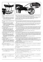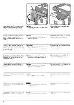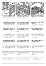
9
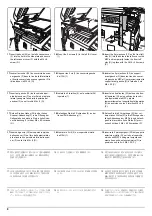
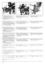
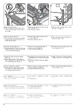
20.
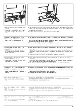
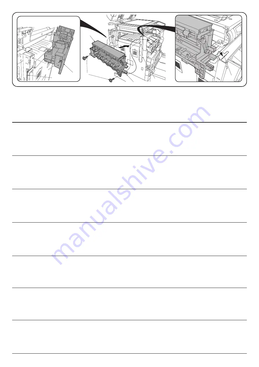
Position the eject unit (H) so that its rail section (34) is inside the MFP, insert the projection (35) on the rear into the hole in the side plate and then
place the front end onto the plate section (37) on the front left stay (G).
NOTICE
When installing the eject unit (H), take care not to pinch the drive unit cable (36).
21.
Fully tighten the 2 M4 × 20 screws (P) that were temporarily fastened in step 19 and secure the front left stay (G).
22.
Secure the eject unit (H) with the 2 M4 × 8 screws (O).
20.
Positionner l'unité d'éjection (H) de sorte que sa partie glissière (34) se trouve dans le MFP, insérer la projection arrière (35) dans le trou de la tôle
latérale puis placer l'extrémité avant sur la partie plaque (37) du support avant gauche (G).
AVIS
À l'installation de l'unité d'éjection (H), attention à ne pas coincer le câble de l'unité d'entraînement (36).
21.
Serrer à fond les 2 vis M4 × 20 (P) provisoirement serrées à l'étape 19 et fixer le support avant gauche (G).
22.
Fixer l'unité d'éjection (H) avec 2 vis M4 × 8 (O).
20.
Coloque la unidad de salida (H) de forma tal que la sección de su carril (34) quede dentro de la MFP, inserte el saliente (35) de la parte posterior en el
orificio de la placa lateral y, a continuación, coloque el extremo frontal sobre la sección de la placa (37) del soporte frontal izquierdo (G).
AVISO
Cuando instale la unidad de salida (H) tenga cuidado de no pinzar el cable de la unidad de accionamiento (36).
21.
Apriete totalmente los 2 tornillos M4 × 20 (P) que ajustó temporariamente en el paso 19 y asegure el soporte frontal izquierdo (G).
22.
Asegure la unidad de salida (H) con los 2 tornillos M4 × 8 (O).
20.
Richten Sie die Auswerfeinheit (H) so aus, dass der Schienenabschnitt (34) im MFP sitzt, setzen Sie den Vorsprung (35) auf der Rückseite in die Öff-
nung der Seitenplatte ein und setzen Sie dann das Vorderteil auf den Plattenabschnitt (37) an der vorderen linken Stütze (G).
HINWEIS
Achten Sie beim Montieren der Auswerfeinheit (H) darauf, dass das Kabel (36) der Antriebseinheit nicht eingeklemmt wird.
21.
Ziehen Sie die in Schritt 19 provisorisch angezogenen 2 M4 × 20 Schrauben (P) vollständig an und sichern Sie die vordere linke Stütze (G).
22.
Befestigen Sie die Auswerfeinheit (H) mit den 2 M4 × 8 Schrauben (O).
20.
Posizionare l'unità di espulsione (H) in modo che la sua sezione di rotaia (34) sia all'interno dell'MFP, inserire la parte sporgente (35) sul retro, nel foro
nella piastra laterale e quindi posizionare il terminale anteriore sulla sezione della piastra (37) sul supporto anteriore sinistro (G).
NOTIFICA
Quando si installa l'unità di espulsione (H), fare attenzione a non schiacciare il cavo dell'unità guida (36).
21.
Stringere completamente le 2 viti M4 × 20 (P) che sono state strette temporaneamente nel punto 19 e fissare il supporto anteriore sinistro (G).
22.
Fissare l'unità di espulsione (H) con le 2 viti M4 × 8 (O).
20.
排出ユニット (H) のレール部分 (34) が MFP 本体の内側にくるようにセットし、後側の突起 (35) を側板の穴に入れ、前側を左前ステー(G) のプレート
部 (37) に乗せる。
注意
排出ユニット (H) を取り付ける時は駆動ユニットの電線 (36) を挟まないように注意する。
21.
手順 19 で仮締めしたビス M4×20(P)2 本を本締めし、左前ステー(G) を固定する。
22.
ビス M4×8(O)2 本で排出ユニット (H) を固定する。
20.
将排纸单元 (H) 的导轨部分 (34) 靠 MFP 主机内侧设置,将后部的突出部 (35) 插入侧板的孔中,将前部放在左前部支架 (G) 的托板部 (37) 上。
注意
安装排纸单元 (H) 时,必须注意不要夹住驱动单元的电线 (36)。
21.
将步骤 19 中临时固定的 2 颗 M4×20 螺丝 (P) 拧紧,以固定左前部支架 (G)。
22.
使用 2 颗 M4×8 螺丝 (O) 来固定排纸单元 (H)。
20.
배출 유니트 (H) 의 레일부분 (34) 이 MFP 본체의 안쪽이 되게 세트하고 뒷쪽의 돌기 (35) 를 측면판 구멍에 넣어 앞쪽 좌측 받침대 (G) 의 플레이트부
(37) 에 얹습니다 .
주의
배출 유니트 (H) 를 부착할 때에는 구동 유니트의 전선 (36) 을 끼지 않도록 주의합니다 .
21.
순서 19 에서 반정도 조인 나사 M4×20(P) 2 개를 완전히 조이고 좌측 앞 받침대 (G) 를 고정합니다 .
22.
나사 M4×8(O) 2 개로 배출 유니트 (H) 를 고정합니다 .
H
H
O
35
36
34
G
37
Содержание UTAX AK 730
Страница 5: ...This page is intentionally left blank ...
Страница 11: ...This page is intentionally left blank ...
Страница 15: ...3NB 3ND 3N0 3NK This page is intentionally left blank ...
Страница 25: ...3NB 3ND 3N0 3NK 1 1 10 This page is intentionally left blank ...
Страница 43: ...3NB 3ND 3N0 3NK 1 2 18 3 Remove tape and pad Figure 1 2 23 Tape Pad ...
Страница 45: ...3NB 3ND 3N0 3NK 1 2 20 This page is intentionally left blank ...
Страница 81: ...3NB 3ND 3N0 3NK 1 3 36 This page is intentionally left blank ...
Страница 157: ...3NB 3ND 3N0 3NK 1 4 76 This page is intentionally left blank ...
Страница 169: ...3NB 3ND 3N0 3NK 1 5 12 This page is intentionally left blank ...
Страница 206: ...3NB 3ND 3N0 3NK 2 2 11 This page is intentionally left blank ...
Страница 246: ...1 1 INSTALLATION GUIDE INSTALLATION GUIDE FOR 4000 SHEETS FINISHER ...
Страница 269: ...INSTALLATION GUIDE FOR FINISHER ATTACHMENT KIT MFP A ...
Страница 283: ...INSTALLATION GUIDE FOR FINISHER ATTACHMENT KIT MFP B ...
Страница 284: ...E F A H G I J B D C ...
Страница 291: ...INSTALLATION GUIDE FOR FINISHER ATTACHMENT KIT PRINTER ...
Страница 295: ...INSTALLATION GUIDE FOR CENTER FOLDING UNIT ...
Страница 312: ...INSTALLATION GUIDE FOR MULTI TRAY ...
Страница 326: ...INSTALLATION GUIDE FOR MULTI TRAY ATTACHMENT KIT PRINTER ...
Страница 330: ...INSTALLATION GUIDE FOR PUNCH UNIT ...

