10
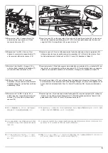
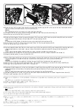
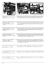
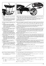
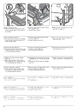
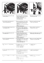
23.
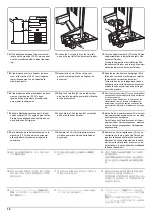
Plug the 3 connectors (38) into the eject unit
(H) and MFP.
24.
Secure the cables with the 2 wire stoppers
(I).
25.
Position the upper front cover (J) so that the screw housing (39) is not touching the front left stay
(G) and align the projections (40) with the 2 holes on the right side of the upper front cover (J)
before attaching the upper front cover (J) and securing it in place with the M4 × 8 screw (O).
23.
Enficher les 3 connecteurs (38) dans l'unité
d'éjection (H) et le MFP.
24.
Fixer les câbles à l'aide des 2 butées de
câble (I).
25.
Positionner le couvercle supérieur avant (J) de sorte que le logement de la vis (39) ne soit pas en
contact avec le support avant gauche (G) et aligner les projections (40) avec les 2 trous du côté
droit du couvercle supérieur avant (J) avant de fixer ce couvercle supérieur avant (J) à l'aide
d'une vis M4 × 8 (O).
23.
Enchufe los 3 conectores (38) en la unidad
de salida (H) y la MFP.
24.
Asegure los cables con los 2 topes para
cables (I).
25.
Coloque la cubierta frontal superior (J) de forma tal que el alojamiento del tornillo (39) no toque el
soporte frontal izquierdo (G) y alinee los salientes (40) con los 2 orificios del lado derecho de la
cubierta frontal superior (J) antes de instalar la cubierta frontal superior (J) y asegurarla en
posición con el tornillo M4 × 8 (O).
23.
Stecken Sie die 3 Stecker (38) in die Aus-
werfeinheit (H) und den MFP.
24.
Befestigen Sie die Kabel mit den 2 Kabelhal-
tern (I).
25.
Positionieren Sie die obere vordere Abdeckung (J) so, dass das Schraubengehäuse (39) nicht
die vordere linke Stütze (G) berührt und richten Sie die Vorsprünge (40) auf die 2 Öffnungen an
der rechten Seite der oberen vorderen Abdeckung (J) aus, bevor Sie die obere vordere Abdeck-
ung (J) anbringen und mit der M4 × 8 Schraube (O) sichern.
23.
Collegare i 3 connettori (38) all'unità di
espulsione (H) e all'MFP.
24.
Fissare i cavi con i 2 fermacavo (I).
25.
Posizionare il coperchio superiore anteriore (J) in modo che l'alloggiamento delle viti (39) non
tocchi il supporto anteriore sinistro (G), e allineare le parti sporgenti (40) con i 2 fori sul lato destro
del coperchio superiore anteriore (J) prima di applicare il coperchio superiore anteriore (J) e fis-
sarlo in posizione con la vite M4 × 8 (O).
23.
コネクター(38)3 個を排出ユニット (H) お
よび MFP 本体に接続する。
24.
ワイヤーストッパー(I)2 個で電線を固定す
る。
25.
前上カバー(J) 左側のビス止め部 (39) が左前ステー(G) に当たらないようセットし、前上カバー
(J) 右側の穴 2 箇所に突起 (40) を合わせてから前上カバー(J) を取り付け、ビス M4×8(O)1 本で
固定する。
23.
使用 3 个接插件 (38) 来连接排纸单元 (H) 以
及 MFP 主机。
24.
使用 2 个电线固定夹 (I) 来固定电线。
25.
设置前上部盖板 (J),注意避免其左侧的螺丝固定部 (39) 碰到左前部支架 (G),将前上部盖板 (J)
右侧的 2 处孔与突出部 (40) 对齐后安装前上部盖板 (J),使用 1 颗 M4×8 螺丝 (O) 来固定。
23.
커넥터 (38) 3 개를 배출 유니트 (H) 및 MFP
본체에 접속합니다 .
24.
와이어 스토퍼 (I) 2 개로 전선을 고정합니다
.
25.
전면 상커버 (J) 좌측의 나사 고정부 (39) 가 좌측 앞 받침대 (G) 에 닿지 않도록 세트하고 전면 상
커버 (J) 우측 구멍 돌기 (40) 2 곳를 맞춰 전면 상커버 (J) 를 부착 , 나사 M4×8(O) 1 개로 고정
합니다 .
38
H
I
J
O
J
40
39
G
Содержание UTAX AK 730
Страница 5: ...This page is intentionally left blank ...
Страница 11: ...This page is intentionally left blank ...
Страница 15: ...3NB 3ND 3N0 3NK This page is intentionally left blank ...
Страница 25: ...3NB 3ND 3N0 3NK 1 1 10 This page is intentionally left blank ...
Страница 43: ...3NB 3ND 3N0 3NK 1 2 18 3 Remove tape and pad Figure 1 2 23 Tape Pad ...
Страница 45: ...3NB 3ND 3N0 3NK 1 2 20 This page is intentionally left blank ...
Страница 81: ...3NB 3ND 3N0 3NK 1 3 36 This page is intentionally left blank ...
Страница 157: ...3NB 3ND 3N0 3NK 1 4 76 This page is intentionally left blank ...
Страница 169: ...3NB 3ND 3N0 3NK 1 5 12 This page is intentionally left blank ...
Страница 206: ...3NB 3ND 3N0 3NK 2 2 11 This page is intentionally left blank ...
Страница 246: ...1 1 INSTALLATION GUIDE INSTALLATION GUIDE FOR 4000 SHEETS FINISHER ...
Страница 269: ...INSTALLATION GUIDE FOR FINISHER ATTACHMENT KIT MFP A ...
Страница 283: ...INSTALLATION GUIDE FOR FINISHER ATTACHMENT KIT MFP B ...
Страница 284: ...E F A H G I J B D C ...
Страница 291: ...INSTALLATION GUIDE FOR FINISHER ATTACHMENT KIT PRINTER ...
Страница 295: ...INSTALLATION GUIDE FOR CENTER FOLDING UNIT ...
Страница 312: ...INSTALLATION GUIDE FOR MULTI TRAY ...
Страница 326: ...INSTALLATION GUIDE FOR MULTI TRAY ATTACHMENT KIT PRINTER ...
Страница 330: ...INSTALLATION GUIDE FOR PUNCH UNIT ...

