121
Analog output (1) adjustment (S-07):
The following steps show how to adjust analog output (1) gain (L-03) and analog output (1) offset (L-04)
through analog output (1) adjustment (S-07).
* Be sure to follow the procedure after analog input (1) gain (L-01) and analog input (1) offset (L-02) adjustment.
-
How to adjust analog output (1) offset (L-06)
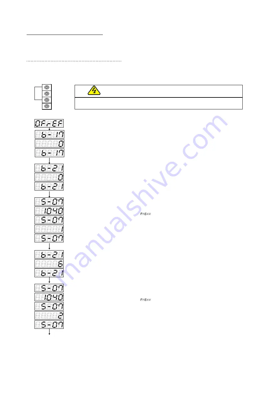
After power-on, press the [MONI/FNC] key to enter the FNC (function selection) mode (LED-FNC is
lit).
- With [JOG/
→
] [
↑
][
↓
] keys, select "S-07". Confirm it with the [SET] key.
- Edit the number with [JOG/
→
] [
↑
][
↓
] keys to enter "1040", and confirm it with the [SET] key.
If entering any value other than "1040",
is displayed.
- "S-07" is displayed again. Confirm it with the [SET] key.
- Edit the number with [JOG/
→
] [
↑
][
↓
] keys to enter "1", and confirm it with the [SET] key.
- "S-07" is displayed again.
With VF66B (DC motor drive) turned off, open the front cover, and cause short circuit between (AOT1)
and (AIN1) terminals of the terminal block [TB1] on the control print board [VFC66-Z] using the Phillips
screwdriver (M3).
Warning
[Short circuiting on terminals]
●
Be sure to turn off VF66B (DC motor drive) before short-circuiting the terminals.
Otherwise, it can result in a risk of electric shock.
Control print board
[VFC66-Z]
terminal block [TB1]
- After pressing the [MONI/FNC] key to enter the FNC (function selection) mode (LED-FNC is lit),
select "b-17" with [JOG/
→
] [
↑
][
↓
] keys. Confirm it with the [SET] key.
- Edit the number with [JOG/
→
] [
↑
][
↓
] keys to enter "0". Confirm it with the [SET] key.
- "b-17" is displayed again.
- With [JOG/
→
] [
↑
][
↓
] keys, select "b-21". Confirm it with the [SET] key.
- Edit the number with [JOG/
→
] [
↑
][
↓
] keys to enter "0", and confirm it with the [SET] key.
- "b-21" is displayed again.
- With [JOG/
→
] [
↑
][
↓
] keys, select "b-21". Confirm it with the [SET] key.
- Edit the number with [JOG/
→
] [
↑
][
↓
] keys to enter "6", and confirm it with the [SET] key.
- "b-21" is displayed again.
- With [JOG/
→
] [
↑
][
↓
] keys, select "S-07." Confirm it with the [SET] key.
- Edit the number with [JOG/
→
] [
↑
][
↓
] keys to enter "1040", and confirm it with the [SET] key.
If entering any value other than "1040",
is displayed.
- "S-07" is displayed again. Confirm it with the [SET] key.
- Edit the number with [JOG/
→
] [
↑
][
↓
] keys to enter "2", and confirm it with the [SET] key.
- When "S-07" is displayed again, analog output (1) gain (L-03) and analog output (1) offset (L-04) are
automatically changed.
- Press the [MONI/FNC] key to display the monitor item.
After adjustment, turn off VF66B (DC motor drive), open the front cover, and remove the wiring installed between (AOT1)
and (AIN1) terminals of the terminal block [TB1] on the control print board [VFC66-Z] using the Phillips screwdriver (M3).
AOT1
GND
AIN1
+10


