☞
Cables are not included in the installation kit.
Connector Blocks
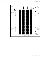
Figure 3-8 shows the connector block that is to be used to add the wiring for the
VP 300.
The connector block has 50 separate punchdown contacts in each column, with
each column wired to an amphenol connector at the side of the block. Column
A is wired to jack 1, column B to jack 2, etc.
Mount the block to the backboard in the location you have specified. Mounting
screws are provided when the block is ordered. Mount the block with the word
“TOP” (embossed in the plastic, located in the upper left hand side of the block)
facing up. Refer to Figure 3-8.
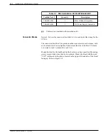
Table 3-7 DAC Installation Kit Part #740-6045-001
Toshiba Part #
Quantity
Description
740-6051-001
740-6050-001
1
1
DAC IO Panel Assembly
DC Power Supply Assembly
Toshiba VP Systems Release 7.1 July, 1994
3-32
Installation and Maintenance Manual
Содержание VP 300
Страница 2: ......
Страница 10: ......
Страница 14: ......
Страница 19: ...Quick Reference Guide Hardware Toshiba VP 300 System Specifications Toshiba VP Systems Release 7 1 July 1994 ...
Страница 20: ...Toshiba VP Systems Release 7 1 July 1994 ...
Страница 52: ...Toshiba VP Systems Release 6 1 February 1993 2 14 Installation and Maintenance Manual ...
Страница 56: ...Toshiba VP Systems Release 7 1 July 1994 ...
Страница 146: ......
Страница 312: ...Toshiba VP Systems Release 7 1 July 1994 ...
Страница 314: ......
Страница 444: ......
Страница 496: ......
Страница 542: ......
Страница 598: ...Toshiba VP Systems Release 6 1 February 1993 ...
Страница 600: ...Toshiba VP Systems Release 6 1 February 1993 ...


