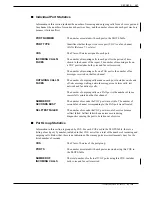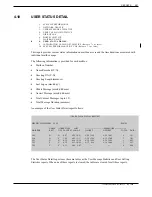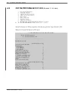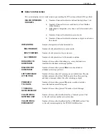
Figures and Tables
Figure
Description
Page
5-1
Alarm Test Flow ..............................................................................................................................
5-23
5-2
Traffic Peg Count Table ..................................................................................................................
5-50
5-3
VP 300 Cabinet Shelf Structure ......................................................................................................
5-75
5-4
VP 300 Cabinet Inside Front View ..................................................................................................
5-76
5-5
VP 300 Cabinet Rear View..............................................................................................................
5-77
5-6
VP 300 Cabinet Inside Rear View ...................................................................................................
5-78
5-7
VP 300 Cardcage with Printed Circuit Assembly (PCA) and Option Control Chip (OCC)...............
5-80
5-8
Fax Application Processor...............................................................................................................
5-84
5-9
Motherboard Assembly ...................................................................................................................
5-86
5-10
Disk Drive Backplane ......................................................................................................................
5-90
5-11
VP 300 Floppy Drive Assembly .......................................................................................................
5-93
5-12
VP 300 Hard Disk Drive Assembly ..................................................................................................
5-96
5-13
VP 300 Power Supply Assembly .....................................................................................................
5-99
5-14
Power Filter Assembly for 120 VAC and 240 VAC Domestic Cabinet ............................................ 5-102
5-15
Power Filter Assembly for 240 VAC International Cabinet .............................................................. 5-103
5-16
Power Filter Assembly for 48 VDC Cabinet .................................................................................... 5-104
5-17
Field Wiring for –48 VDC Powered VP 300..................................................................................... 5-106
5-18
Option Control Chip (OCC) Assembly ............................................................................................. 5-109
5-19
Option Control Chip (OCC) Location in VP 300 Cabinet ................................................................. 5-110
5-20
Sequence the Toshiba VP System Follows to Screen Calls ........................................................... 5-112
5-21
Ring/No Answer Tone Timing Failure ............................................................................................. 5-115
Table
Description
Page
5-1
Abbreviations for Channel/Port State ..............................................................................................
5-21
5-2
Boot ROM Diagnostic Errors ...........................................................................................................
5-51
5-3
Hardware Error Types and Remedies .............................................................................................
5-56
5-4
Storage Disk Drives.........................................................................................................................
5-98
5-5
Transaction Types ........................................................................................................................... 5-127
5-6
CDR Status That Can Be Logged .................................................................................................. 5-128
5-7
Information Logged by Transaction Type ........................................................................................ 5-137
5-8
Call Detail Record Size by Transaction Type .................................................................................. 5-139
5
MAINTENANCE
Toshiba VP Systems Release 7.1 July, 1994
Содержание VP 300
Страница 2: ......
Страница 10: ......
Страница 14: ......
Страница 19: ...Quick Reference Guide Hardware Toshiba VP 300 System Specifications Toshiba VP Systems Release 7 1 July 1994 ...
Страница 20: ...Toshiba VP Systems Release 7 1 July 1994 ...
Страница 52: ...Toshiba VP Systems Release 6 1 February 1993 2 14 Installation and Maintenance Manual ...
Страница 56: ...Toshiba VP Systems Release 7 1 July 1994 ...
Страница 146: ......
Страница 312: ...Toshiba VP Systems Release 7 1 July 1994 ...
Страница 314: ......
Страница 444: ......
Страница 496: ......
Страница 542: ......
Страница 598: ...Toshiba VP Systems Release 6 1 February 1993 ...
Страница 600: ...Toshiba VP Systems Release 6 1 February 1993 ...

