background image

Toshiba VP Systems Release 7.1

July, 1994

MAINTENANCE

5-73

Table 5-3   Hardware Error Types and Remedies (continued)

Error Type:Name

Source

Remedy

Priority

44:   CPU/VCU

Request/Reply
Checksum Error

A protocol error
occurred between the
CPU and VCU on the
control bus.

Contact Toshiba Technical Support.

3

DATA-1  = 

DATA-2,
DATA-3,
DATA-4  =         

NUMBER OF RETRIES ATTEMPTED BEFORE TRANSACTION
SUCCEEDED OR ABANDONED (MAXIMUM OF 3).

FAILURE REASON FOR EACH ATTEMPT:
01  =
02  =

03  =

04  =

05  =
06  =

NO ERROR (RETRY SUCCEEDED)
CONTROL BUS TIMEOUT ATTEMPTING TO READ
CPU CB STATUS REGISTER
CONTROL BUS TIMEOUT ATTEMPTING TO READ
VCU SHARED RAM
CONTROL BUS TIMEOUT ATTEMPTING TO WRITE
VCU SHARED RAM
INCORRECT CHECKSUM ON VCU REPLY BUFFER
VCU DETECTED CHECKSUM ERROR ON CPU
REQUEST BUFFER

45:   VCU Reply

Language Set
Error

The VCU has replied
that there is an error
in a language set.

Contact Toshiba Technical Support.

3

DATA-1
DATA-2 — BIT MAP HI BITS
DATA-3 — BIT MAP HI BITS

=  THIS ERROR NUMBER
=  LOAD FAULT
=  NOT LOADED

Содержание VP 300

Страница 1: ...and retrieval systems without permission in writing from Toshiba America Information Systems Inc The following are trademarks of Toshiba America Information Systems Inc TOSHIBA VP The following are registered trademarks of VMX Inc VMX Voicenet The following are trademarks of VMX Inc IntraMessaging Personal Assistance Adaptive Integration NOTE Whenever the term VP 300s 300 is encountered in this ma...

Страница 2: ......

Страница 3: ...Pin Assignments 3 15 3 6 Communicating with the System 3 21 3 7 VP 300 Hardware Installation 3 22 3 8 Rack Mount Installation 3 25 3 9 Software Installation 3 29 3 10 Connecting the Phone System to the VP 300 3 31 3 11 VP 300 Testing 3 36 3 12 Testing the Installation and Telephone Changes 3 45 Chapter 4 Reports 4 1 Listing and Clearing Reports 4 1 4 2 System Performance Report 4 4 4 3 Network Tra...

Страница 4: ... Chapter 6 Procedures 6 1 Electronic Feature Delivery Removal 6 1 6 2 Backup Procedures 6 2 6 3 Restore Procedures 6 21 6 4 Floppy Directory 6 43 6 5 Errors 6 44 6 6 Hard Disk Procedures 6 45 Chapter 7 Standard DTMF Integration 7 1 Standard DTMF Integration vs Adaptive Integration 7 1 7 2 Standard DTMF Integration 7 2 7 3 VP 300 PBX Interaction in Standard DTMF Integration 7 3 Chapter 8 Adaptive I...

Страница 5: ...X 200 Digital 10 1 1 10 2 Mitel SX 100 and SX 200 Analog 10 2 1 10 3 Mitel SX 2000 10 3 1 Chapter 11 DAC Installation 11 1 FCC Notice to the Users 11 1 11 2 DAC Overview 11 2 11 3 Installation 11 5 Toshiba VP 300 Installation Maintenance Manual Toshiba VP Systems Release 7 1 July 1994 ...

Страница 6: ... for Domestic Installation 3 4 3 1 1 VP 300 DC Cover 3 8 3 2 Field Wiring for 48 VDC Powered VP 300 3 9 3 3 First and Second RS 232C Serial Port Cable Pin Outs for Connection to Terminal Equipment 3 12 3 4 VP 300 to External Modem Pinouts 3 13 3 5 Connecting to the VP 300 s Internal Modem 3 14 3 6 VP 300 Cabinet Installed in 19 Rack 3 25 3 7 Typical VP 300 Connections 3 31 3 8 Connector Block 3 33...

Страница 7: ...tegration 8 1 VP 300 PBX Interaction in Enhanced DTMF In band Integration Environment 8 3 8 2 VP 300 PBX Interaction in RS 232C Data Link Integration Environment 8 4 Chapter 9 Centrex SMDI SMSI Adaptive Integration 9 1 The VP 300 SMDI and Centrex Connection 9 2 Chapter 10 Mitel Integration 10 1 1 Diagram of the Superset 4 Telephone 10 1 26 10 2 1 Diagram of the Superset 4 Telephone 10 2 21 10 3 1 ...

Страница 8: ...by Transaction Type 5 139 Chapter 10 Mitel Integration 10 1 1 Test Equipment 10 1 24 10 1 2 Mitel SX 200 Digital Requirements 10 1 45 10 1 3 Mitel SX 200 Digital Configuration 10 1 45 10 1 4 VP 300 Configuration Changes for MWI and CPI 10 1 46 10 1 5 After All Changes Have Been Made for MWI and CPI 10 1 47 10 1 6 Installing and Testing 10 1 47 10 1 7 Test Equipment 10 1 48 10 2 1 Test Equipment 10...

Страница 9: ...les Table Description Page Chapter 11 DC Installation 11 1 SLOTS Table Configuration Changes 11 6 11 2 DAC I O Panel DP EXT Connections 11 12 Toshiba VP 300 Installation Maintenance Toshiba VP Systems Release 7 1 July 1994 ...

Страница 10: ......

Страница 11: ...rds 1 10 Voice Control Unit VCU 1 10 Central Processing Unit CPU 1 10 Power Supply Unit PSU 1 11 Shelf A Motherboard 1 12 Option Control Chip OCC 1 12 1 3 Shelf B and Shelf C Slots 1 13 Hard Disk Drives HD 1 14 Load Backup Device 1 15 Shelf B Motherboard 1 15 Shelf C Motherboard 1 15 1 4 Additional Subsystems 1 16 System Terminal Port 1 16 Fan Tray 1 16 Power Line Filter 1 16 System Alarm Relays 1...

Страница 12: ...1 2 VP 300 Cabinet Inside Front View 1 3 1 3 VP 300 Cabinet Rear View 1 4 1 4 VP 300 Cabinet Inside Rear View 1 5 1 5 Diagram of Slots in Shelf A of the VP 300 1 8 1 6 Diagram of Slots in Shelves B and C of the VP 300 1 13 Table Description Page 1 1 VP 300 VP Subsystems 1 6 1 2 Power Supply Unit DC Voltages 1 11 1 HARDWARE ...

Страница 13: ...is chapter you will find the following Quick Reference Guide containing the system specifications for the VP 300 Overview of the VP 300 hardware Cabinet structure Shelf A and Shelf B Description of the VP 300 subsystems Diagrams of the front and rear views of the VP 300 cabinet Diagrams of the contents of Shelves A and B ...

Страница 14: ......

Страница 15: ...tandard with multiple disk systems Storage Ports 4 64 Release 5 4 or later 32 96 VP 300XL Release 7 1 or later 4 48 Release 5 3 Port Increments 4 or 8 Release 5 4 or later 4 Release 5 3 Maximum Cabinets 10 per System Classes of Service COS 255 Release 6 1 or later 128 prior to Release 6 1 Cabinet Specifications Cabinet Dimensions Height 37 5 inches 95 3 cm Width 17 5 inches 44 5 cm Depth 19 5 inch...

Страница 16: ...Alarm Types Major Alarm Minor Alarm Temperature Alarm Alarm Temperature 50F or 122F 10C or 50C Environmental Requirements Temperature Operating Sea Level 50F 10C to 104F 40C Non operating 50F 10C to 129F 54C Gradient operating 50F 10C per hour maximum Gradient non operating 68F 20C per hour maximum Humidity Operating 20 80 non condensing Atmosphere Particulate Matter max 80 micrograms per cubic mi...

Страница 17: ...0 type 2 wire DID type optional DAC Port Connector 50 pin telco 4 ports per connector with 4 port LIC 8 ports per connector with 8 port LIC rear access 16 ports per connector for DID type from DAC panel System Serial Port RS 232C auto baud rate select DB25 300 19 200 bps RS 232C Integration RS 232C 1200 bps DB25 Port Internal Modem 300 1200 bps Bell 103 212A one per cabinet accessible from any tel...

Страница 18: ...er Current All 6 DC outputs auto recovery Over Voltage All 6 DC outputs circuit breaker trip manual recovery Over Temperature Circuit breaker trip manual recovery Electrostatic Discharge 25 kV to chassis without disruption of operation ESD Power Line Disturbance IEEE 587 1 5 kV maximum without disruption of operation Telephony Port Isolation 3 750 VAC any port to ground System Adjustments Cabinet ...

Страница 19: ...Quick Reference Guide Hardware Toshiba VP 300 System Specifications Toshiba VP Systems Release 7 1 July 1994 ...

Страница 20: ...Toshiba VP Systems Release 7 1 July 1994 ...

Страница 21: ...um Clearances Front 22 inches 55 9 cm Rear 6 inches 15 2 cm Side 1 inch 2 5 cm Top none Inner Structure The top shelf Shelf A contains the Line Interface Cards LIC Fax Application Processor Fax card Release 7 1 or later Direct Access Cards DAC Telemarketing Line Cards TLC Integration Cards Voice Control Unit VCU Central Processing Unit CPU and the power supply unit PSU Consult Toshiba Telecom Prod...

Страница 22: ...A8 LIC TLC DAC FAX or Integration Card A7 LIC TLC DAC FAX or Integration Card A6 LIC TLC DAC FAX or Integration Card A5 LIC TLC DAC FAX or Integration Card A4 LIC TLC DAC FAX or Integration Card A3 LIC TLC DAC FAX or Integration Card A2 LIC TLC DAC FAX or Integration Card A1 LIC TLC DAC FAX or Integration Card A15 Fan Assembly B1 B2 B3 B4 B5 Load Backup Device System Voice Disk Drive 2 C1 C2 C3 C4...

Страница 23: ...C4 LIC 4 LIC 8 Front Door Fan Tray Disk Drive Assembly LIC8 LIC4 VCU Slot A13 System Terminal Port SP1 Connector CPU Slot A14 ON OFF Switch Power Supply Unit Load Backup Device Floppy Drive Floppy Signal Cable Figure 1 2 VP 300 Cabinet Inside Front View LIC8 ...

Страница 24: ...onnection J1 Reserved RS 232C Ports J3 and J4 Port B J2 Alarm Port J5 50 pin 25 pair Amphenol connectors Cable Tiedown Points Tapped Mounting Holes for securing DAC panel Earth Ground Connection Point Power Cord Power Receptacle J6 J1 J2 J3 J4 J5 P11 P12 P10 P9 P8 P7 P6 P5 P4 P3 P2 P1 Figure 1 3 VP 300 Cabinet Rear View ...

Страница 25: ...VP 300 Cabinet Inside Rear View Main Motherboard shelf A Fan Tray Power Harness SCSI Bus Jumper Cable 3 places Disk Drive Motherboard shelf B Disk Drive Motherboard shelf C Maintenance Port Cable Main System Power Harness EMI Line Filter Main Disk Drive Power Harness ...

Страница 26: ...ace card VP 300 allows recording by the first port of a TLC only if the TLC is in slot 1 300 6032 003 Telemarketing Line Card TLC For 49 64 ports File system manager SCSI bus control and voice bus control 300 6001 003 A four port two wire loopstart telephone line interface card 300 6002 001 For 65 96 ports for the VP 300XL Release 7 1 or later File System manager SCSI bus control 300 6001 004 and ...

Страница 27: ...an upgrade 740 6010 001 Load Backup Device Floppy Disk Drive Backplane boards for interconnecting system modules and system power distribution 300 6005 001 Motherboards MB Power conversion from system input power to six regulated DC voltages 740 6016 001 740 6017 001 740 6027 001 Power Supply Unit PSU 120 VAC 240 VAC 48 VAC 740 6003 001 300 6006 001 Shelf C Shelf A Shelf B Part Number Description ...

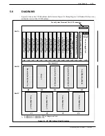
Страница 28: ... Release 5 3 Release 6 1 and later LIC FAX A1 A12 4 port only A1 A12 4 or 8 port TLC N A A1 A12 DAC A1 A11 A1 A11 RIC SLIC MIC Rel 6 1 A9 A12 A1 A12 ATTIC Meridian Rel 6 1 A9 A11 A1 A11 INTEGRATION CARDS Fax Application Processor fax is available beginning with Release 7 1 Figure 1 5 Diagram of Slots in Shelf A of the VP 300 For Release 5 3 cannot have TLC or Integration Card For Release 5 3 canno...

Страница 29: ...er TLC ports in the system are play only ports When recording is attempted on other ports the VP 300 prompts Messages may not be recorded at this time No storage is available The first TLC must be installed in slot A1 Standard line cards can be installed in slots beyond the TLC cards A VP 300 at Release 6 1 and later may contain a maximum of 64 ports including TLC and LIC ports The TLC is FCC part...

Страница 30: ...the VCU and the optional integration cards The CPU contains four serial I O ports The first serial port is shared between the internal modem and the system terminal port which is accessed at the rear connector J1 or the front connector SP1 As a modem port the first serial port can be connected to any telephone port under system software control The internal modem is a Bell 103A compatible 300 bps ...

Страница 31: ...upts the CPU as a warning of loss of primary power allowing controlled shutdown of the VP 300 The PSU provides the system reset signal This signal is activated at power up and resets all boards in the system The PSU provides a protective circuit breaker for primary power This circuit breaker also acts as the system power switch The circuit breaker is tripped for primary overcurrent power supply ov...

Страница 32: ...ring circuits of a telephone network via connector P1 Option Control Chip OCC The Option Control Chip OCC is located on the Motherboard in shelf A directly behind the PSU The OCC holds information concerning the system configuration and software options the VP 300 is equipped with The OCC must always remain with the system it was purchased for If the Motherboard requires replacement the OCC must b...

Страница 33: ...e system voice and voice drives are loaded into the slots in the following order B3 B4 C1 C2 C3 and C4 A one drive system has a system voice drive installed in slot B3 a two drive system has system voice drives installed in slots B3 and B4 a three drive system has system voice drives installed in slots B3 and B4 and a voice drive installed in slot C1 etc Toshiba VP Systems Release 7 1 July 1994 HA...

Страница 34: ...nd system prompts is automatically provided when a second system disk is installed Hot Standby Redundancy is not available when only one system disk is installed Optional software enhancements offer redundancy for names greetings and messages in any system containing two or more disk drives When Names and Greetings Redundancy and Message Redundancy are installed names greetings and messages are ma...

Страница 35: ...through B5 This Motherboard distributes 5V and 12V power to slots B1 through B5 It includes an ID signal field for each slot This ID field is used by the plug in disk assemblies for SCSI bus ID selection Slot B5 is used for the load backup device and includes SCSI bus signal connections and power connections In the case of a floppy device installed in this slot only power is provided from the Moth...

Страница 36: ...the rear of the cabinet The AC system power cord plugs into the power line filter The power line filter prevents electro magnetic interference EMI from entering the primary power lines Some chassis disassembly is required to replace the power line filter The voltage rating of the power line filter must agree with the input voltage rating of the PSU In 48VDC systems the power cord is integral with ...

Страница 37: ...sions 2 7 Called Extensions 2 8 Trunks 2 8 Trunk Redirection 2 8 Trunk Selection 2 9 Ordering Phone System Changes 2 9 2 5 Implementing the VP 300 on PBXs Without DIL Feature 2 12 Upgrade the PBX to a Feature Package Offering the DIL Feature 2 12 Use DID Numbers 2 12 Place the Console in Night Mode 2 12 Arrange for Trunks to Call Divert to the VP 300 Ports 2 13 Figures Figure Description Page 2 1 ...

Страница 38: ...s connection to the phone system the changes required and how to order them It assumes familiarity with some PBX concepts Changes need to be made to the phone system for the VP 300 Some are changes to the PBX others are done in the Central Office CO This may require lead time Work with the client to determine who will make the changes and how long they will take Prepare a schedule so everyone know...

Страница 39: ...d in a hunting arrangement within the PBX The hunt group may be circular or linear terminal according to the requirements of each particular PBX This assures that callers are answered by the first available port The mode AX CX or MX of the VP 300 port determines how calls are answered by the VP 300 Refer to the Configuration manual SLOTS Integrated Installations Different methods are used to integ...

Страница 40: ...en answer the call with the appropriate greeting or response Once the station identity and condition for the forwarded call is known an analog port answers the call and provides all remaining messaging functions The proprietary line card is used to turn ON or OFF message waiting indicators Answering Incoming Calls The VP 300 can answer all or a portion of a company s incoming calls Trunks can be d...

Страница 41: ... 300 hunt group to take a message Ports receiving forwarded calls are configured in CX mode The VP 300 does not attempt to call the extension number entered by the caller but immediately goes to that extension s mailbox and offers to take a message The attendant may also extend callers to a VP 300 port to allow them to leave a voice message The port is configured as MX mode As with CX mode it does...

Страница 42: ... the survey Use the results of the survey and the type of application to determine the necessary changes Schedule and track these changes using the checklist found in the INSTALLATION chapter Testing the Installation and Telephone Changes For convenience we separated CO trunk changes from PBX changes The following sections discuss changes that may be required and guidelines for ordering the change...

Страница 43: ... the VP 300 by using PBX traffic data and the traffic engineering tables The tables are designed to help decide how to use the VP 300 most effectively for a given situation After collecting the traffic data it may be necessary to order changes from the telephone company to add or alter the number of trunks Splitting Trunk Groups If one two way trunk group will be separated into two or more groups ...

Страница 44: ...isconnection of telephone company provided services and equipment We hereby acknowledge that the VP 300 supplier may obligate us for installation and other charges that may appear on our telephone bill This authorization does not preclude our ability to act on our own behalf as necessary Please contact contact name of the VP 300 supplier at address phone number and extension if you have any questi...

Страница 45: ...alls on hold Transfer calls Forward calls 4 Remove any type of call waiting features from the VP 300 port extensions If configuring ports for outcalling to network locations for off site message notification or for off site alarm calls make sure the port extensions are not restricted from making calls to these locations e g toll restriction 5 Set up a hunt group for each group of port extensions c...

Страница 46: ...ks Possible changes to the PBX trunk programming include redirecting trunks to the VP 300 and assuring any trunking changes do not affect the selection of trunks for outgoing calls No changes need to be made to the DID trunking or programming in the PBX Trunk Redirection Trunks are directed to the VP 300 via a PBX feature Many PBX manufacturers call this feature DIL Direct In Lines or DIT Direct I...

Страница 47: ...your company is not the PBX provider order changes from the PBX vendor on behalf of the customer Provide a Service Provider Letter Figure 2 4 to the PBX vendor indicating the changes needed to the PBX for the VP 300 and schedule the changes If possible try to use the PBX s terminology when requesting these changes You may also want to provide them with information from this chapter Review the prev...

Страница 48: ...There should not be any call waiting features associated with these extensions There should be no toll restriction on all specified extensions c The single line extensions should be placed in a circular hunt group Please make the pilot number easy to dial and to remember d When all members of the hunt group are busy subsequent calls should be overflowed to PBX console attendant defined extension D...

Страница 49: ...cify the number of extensions for each hunt group For example hunt group 1 6 extensions hunt group 2 2 extensions 5 May not be available for all PBXs If possible and desired include this item 6 If there is more than one group of trunks specify the trunks for each hunt group Hunt group 1 Trunks Hunt Group 2 1 800 337 1100 555 3700 1 800 337 1101 555 3701 555 3702 555 3703 7 Tailor this section to t...

Страница 50: ...ossibly not the most practical Use DID Numbers Some customers may already have a block of DID numbers but do not wish to pay for DID numbers and trunks for all employees Callers may be given a number that is a DID extension answered by the VP 300 This is especially suitable where a second number not the main company number is to be established for company employees friends family and frequent call...

Страница 51: ...oup The call diverter answers the trunk and calls through the PBX the VP 300 hunt group number The appropriate number of VP 300 ports as well as one additional extension per trunk to be diverted to the VP 300 are required The call diverter that operates satisfactorily in this situation is the BUSCOM 2008 RD manufactured by MetroTel Because this diverter ordinarily allows remote turn off by pressin...

Страница 52: ...Toshiba VP Systems Release 6 1 February 1993 2 14 Installation and Maintenance Manual ...

Страница 53: ... LIC4 50 Pin Connector Pin outs 3 16 Eight Port Line Interface Card LIC8 and Telemarketing Line Card TLC 50 Pin Connector Pin outs 3 17 Direct Access Card DAC 50 Pin Connector Pin outs 3 18 Direct Access Card I O Panel DP EXT Connector Pin outs 3 19 Direct Access Card I O Panel Power Connector P6 Pin Assignments 3 19 External Alarm Port J5 Pin outs 3 20 3 6 Communicating with the System 3 21 Local...

Страница 54: ... s Internal Modem 3 14 3 6 VP 300 Cabinet Installed in 19 Rack 3 25 3 7 Typical VP 300 Connections 3 31 3 8 Connector Block 3 33 3 9 Cabinet to Block Connection 3 34 Table Description Page 3 1 Input Circuit Current Capacity 3 5 3 2 Input Power Requirements 3 6 3 3 Equipment Provided by Distributor 3 9 3 4 DCE Pin outs for RS 232C Terminal to VP 300 Cable Connections 3 11 3 5 External Modem Pin out...

Страница 55: ... as described in the Installation Requirements section of this chapter Included in this chapter are the following sections Receiving the equipment Installation requirements PBX preparation Hardware installation Connecting terminals Pin Assignments Communicating with the system Software installation Connecting the PBX to the VP 300 Testing the VP 300 for proper installation Toshiba VP Systems Relea...

Страница 56: ...Toshiba VP Systems Release 7 1 July 1994 ...

Страница 57: ...to Toshiba In the event of equipment damage negotiate claims directly with the carrier Unpacking the Cabinet Follow the steps below to unpack the cabinet After unpacking the cabinet collect and save all packing materials cartons foam inserts shipping pallet etc as they are reusable Do not take the cabinet off the shipping pallet unless the unpacking is being done at the installation site Visually ...

Страница 58: ...nt section from the pallet and place the cabinet on the shipping pallet 4 Replace and lock the front door 5 Resecure the front pallet section against the front door using two pallet bolts 6 Replace the plastic bag over the cabinet 7 Replace the door key and power supply cord in the documentation bag and tape bag to top of chassis 8 Replace the foam inserts and cardboard container 9 Tape the top of...

Страница 59: ...refer to PREPARING THE PHONE SYSTEM in this manual Site Requirements Install the VP 300 in a dust free location Keep the VP 300 separate from other equipment that may produce heat generate strong magnetic fields or produce vibration If space and environment permit install the VP 300 in the telephone equipment room Place the cabinet to permit front access and ventilation on all sides The air filter...

Страница 60: ... SERVICE OF FIELD REPLACEABLE UNITS SIDE ACCESS NOT REQUIRED ACCEPTABLE ENVIRONMENT EQUIPMENT ROOM OFFICE ENVIRONMENT FLOOR LOADING 220 POUNDS MAX MAX HEAT DISSIPATION 3412 BTUs HR DEDICATED BRANCH CIRCUIT REQUIREMENT VOLTAGE 120 VAC 240 VAC 48 VAC CURRENT 20A 15A 35A PLUG TYPE NEMA 5 15P NEMA 6 15P FLYING LEADS TOP VIEW Figure 3 1 VP 300 Floor Plan for Domestic Installation 44 00 6 00 WALL 19 50 ...

Страница 61: ...d equipment grounding conductors shall have a continuous outer finish that is either green or green with one or more yellow stripes The equipment grounding conductor is to be connected to ground at the service equipment Verify the wall power outlet conforms to the following UL requirement The attachment plug receptacles in the vicinity of the product or system are all to be of a grounding type and...

Страница 62: ...uire the same amount of power regardless of their storage capacity The following example shows the calculation of the input power requirements for an 8 port system equipped with two line cards one integration card and two voice system disk drives Base cabinet 150 W Two 4 port line cards 20 W 1 integration card 10 W 2 voice system disk drives 50 W Total input power 230 W Total VA rating 1 5 x 230 3...

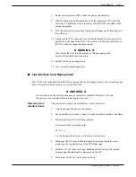
Страница 63: ...onal Electrical Code NEC which specifies regulations for this type of installation Use three conductor 10 gauge cable when field wiring the 48 VDC powered VP 300 Follow NEC regulations when selecting suitable wiring material Following are the steps for installation 1 Locate the VP 300 near the 48 VDC power source 2 Turn OFF the power to the DC power source outlet where the VP 300 will be connected...

Страница 64: ...P Systems Release 7 1 July 1994 3 8 Installation and Maintenance Manual Figure 3 1 1 VP 300 DC Cover DC Filter Assembly Positive Lead Negative Lead Cover Conduit Conduit Strain Relief Ground Lead Terminal Block ...

Страница 65: ...llation and update must be available at the customer site During installation an RS 232C cable is required to connect the terminal to the VP 300 This terminal may be connected to the SP1 connector located in the front of the chassis or at J1 in the rear of the chassis If the terminal is to be permanently installed with the system connect to J1 If the terminal is used temporarily during installatio...

Страница 66: ...E SYSTEM chapter of this manual Refer to that chapter for PBX database changes Setting up hunt groups Directing trunks to the VP 300 Before continuing with the installation assure that the appropriate PBX changes have been made and tested Toshiba VP Systems Release 7 1 July 1994 3 10 Installation and Maintenance Manual 3 3 ...

Страница 67: ... CAT as terminal only no procedures Connect the terminal teleprinter to the system terminal port Two connections to the system terminal port allow for convenient access the front connection SP1 for temporary access and the rear connection J1 for permanent access Toshiba recommends that the terminal teleprinter have the capability to make a hard copy printout RS 232C Terminal to VP 300 Cable Connec...

Страница 68: ...e used if a dedicated modem connection is required or if a modem of baud rate different from the VP 300 internal modem is required A modem that supports standard baud rate 300 to 9600 baud may be connected to the VP 300 System Terminal Port Table 3 5 External Modem Pin outs Modem Pin Number VP 300 Pin Number Modem Signal Name Function VP 300 Name Function 2 3 5 4 7 8 20 3 2 4 5 7 20 8 Transmit Dat...

Страница 69: ...nternal modem using 5 1 Call the VP 300 2 When the VP 300 answers enter 5 3 After the high pitched tone enter the code to connect to the modem ATD The code may vary depending on interface and modem manufacturer If you do not hear a high pitched tone repeat steps 1 and 2 4 Hang up the receiver if step 3 was successful The VP 300 automatically adjusts to the modem s baud rate which must be either 30...

Страница 70: ...e code may vary depending on interface and modem manufacturer If you do not hear a high pitched tone repeat steps 1 through 3 5 Hang up the receiver if step 4 was successful The VP 300 automatically adjusts to the modem s baud rate which must be either 300 or 1200 baud Code may vary depending on interface and modem manufacturer Toshiba VP Systems Release 7 1 July 1994 3 14 Installation and Mainten...

Страница 71: ...7 use a 50 pin male telco connector with the following pin arrangement The following pages contain charts showing the pin assignments for the following Line Interface Card LIC Telemarketing Line Card TLC Direct Access Card DAC External Alarm Port J5 50 Pin Male Telco Connector Pinouts 26 1 50 25 3 5 ...

Страница 72: ... slot A1 it uses 50 pin telco connector P1 if installed in slot A2 it uses connector P2 etc 50 Pin Number Signal Function 50 Pin Number Signal Function 1 2 3 4 5 6 7 8 9 10 11 12 13 14 15 16 17 18 19 20 21 22 23 24 25 RING1 RING2 RING3 RING4 26 27 28 29 30 31 32 33 34 35 36 37 38 39 40 41 42 43 44 TIP1 TIP2 TIP3 TIP4 45 46 47 48 49 50 Toshiba VP Systems Release 7 1 July 1994 3 16 Installation and ...

Страница 73: ...LC is installed in slot A1 it uses 50 pin telco connector P1 if installed in slot A2 it uses connector P2 etc 50 Pin Number Signal Function 50 Pin Number Signal Function 1 2 3 4 5 6 7 8 9 10 11 12 13 14 15 16 17 18 19 20 21 22 23 24 25 RING1 RING2 RING3 RING4 26 27 28 29 30 31 32 33 34 35 36 37 38 39 40 41 42 43 44 TIP1 TIP2 TIP3 TIP4 45 46 47 48 49 50 RING5 RING 7 RING6 RING8 TIP5 TIP6 TIP7 TIP8 ...

Страница 74: ...0 pin telco connector If a DAC card is installed in slot A1 it uses 50 pin telco connector P1 if installed in slot A2 it uses connector P2 etc 50 Pin Number Signal Function 50 Pin Number Signal Function 1 2 3 4 5 6 7 8 9 10 11 12 13 14 15 16 17 18 19 20 21 22 23 24 25 RING1 RING2 48V1 RING3 26 27 28 29 30 31 32 33 34 35 36 37 38 39 40 41 42 43 44 TIP1 TIP2 TIP3 TIP4 45 46 47 48 49 50 RING4 48V3 48...

Страница 75: ...g is the pin assignment for the DAC I O panel power connector P6 Pin Function 1 GND 48 VDC 2 50 Pin Number Signal Function 50 Pin Number Signal Function 1 2 3 4 5 6 7 8 9 10 11 12 13 14 15 16 17 18 19 20 21 22 23 24 25 1RING1 1RING2 1RING3 1RING4 26 27 28 29 30 31 32 33 34 35 36 37 38 39 40 41 42 43 44 1TIP1 1TIP2 1TIP3 1TIP4 45 46 47 48 49 50 2RING1 2RING3 2RING2 2RING4 2TIP1 2TIP2 2TIP3 3RING1 3...

Страница 76: ...ng an alarm condition Pins 3 and 8 are linked together to provide a loop This may be used as a confirmation that an alarm cable is installed Pins 4 5 and 9 are connected to cabinet ground These pins may be jumpered to a relay contact if closure to ground is required Both Relay A and Relay B are rated at 48 V DC maximum 0 5 Amp maximum The link loop is rated at 12 V DC maximum 200 ma maximum Pin Si...

Страница 77: ...locally connected 1 Connect terminal to either front or rear connector of the system terminal port 2 Turn ON the terminal Set the baud rate by repeatedly pressing Enter 3 Press The Password prompt is displayed Toshiba does not supply passwords administrative maintenance and report for new systems When the password prompt is displayed press For security new system passwords should be created as soo...

Страница 78: ...LED ON If a circuit board s diagnostic selftest is successful the green LED is turned ON If the green LED does not come on within five minutes after powering up or reset replace the circuit board 3 Operational Phase red LED OFF green LED ON The downloaded operational software turns OFF the red LED indicating that the circuit board is operational 4 Activity LED yellow LED ON or OFF The yellow LED i...

Страница 79: ... section describes the results of this diagnostic Turn ON your terminal and set the baud rate to any of the valid rates 300 600 1200 2400 4800 9600 or 19200 At any of these baud rates the VP 300 prints or displays the diagnostic status Turn ON the power to the cabinet Immediately following power up press repeatedly to establish the baud rate If the baud rate is not established at this time the sys...

Страница 80: ...et the error code and select the maintenance action required Wait for the operating system to load and the diagnostic selftesting to finish If the tests complete successfully the VP 300 displays INITIALIZING PORTS PORT INITIALIZATION DONE Proceed to the software installation Enter Enter CPU Model 300 6004 101 Rev XX 05MB 1200 BAUD MODEM BOOTING FROM HARD DISK XBOOT SYSTEM SOFTWARE RELEASE L X X X ...

Страница 81: ... screws supplied in Toshiba Rack Mount Kit VP 300 8 mounting screws supplied by rack manufacturer 2 rack mounting brackets one each side supplied in Toshiba Rack Mount Kit 2 support rails supplied by rack manufacturer Figure 3 6 VP 300 Cabinet Installed in 19 Rack Toshiba VP Systems Release 7 1 July 1994 INSTALLATION 3 25 3 8 ...

Страница 82: ... VP 300 is currently in service make sure that all cables connected to the back of the cabinet are long enough to reach the cabinet when it is mounted in the rack The front and back of the rack must remain open to insure proper air flow through the cabinet Mount the cabinet low enough in the rack so that any service person can easily service the cabinet while standing on the floor Installation The...

Страница 83: ...rack vertical rails in order to line up with the holes in the VP 300 rack mounting brackets The preceding step is not necessary if the rack has threaded holes in the vertical mounting rails 9 Two people are needed to move the cabinet into the rack Lift the partially empty cabinet onto the support rails in the rack You may need to remove the leveling feet on the bottom of the cabinet so that the ca...

Страница 84: ...nce they may need to be reconnected exactly as they were 6 Two people are needed to remove the cabinet from the rack Lift the partially empty cabinet out of the rack and place it on the floor 7 Install all assemblies removed in step 4 and secure them to the cabinet Refer to MAINTENANCE Hardware Removal for instructions on installing assemblies 8 Remove the rack mount hardware 9 If the VP 300 is to...

Страница 85: ...ne the database Answer Y when the VP 300 asks if you want to save the configuration to diskette Follow the VP 300 s directions to insert the floppy configuration diskette in the drive Using UPDATE Verifying the Configuration Database After you finish the system configuration the terminal again displays the prompt To get a printout of the database enter the UPDATE program At the prompt type UP The ...

Страница 86: ...the Configuration Database You can modify add or delete system configuration data When the terminal or teleprinter displays the prompt type UP and press to enter the UPDATE program At the prompt you may enter an UPDATE command Refer to the Configuration manual UPDATE TABLE Understanding Update ...

Страница 87: ...minated on a 66M connector block or equivalent for ease of installation and fault isolation Refer to the following diagram Verifying The following equipment is necessary for installation of the VP 300 Equipment PBX extensions associated with the VP 300 to be terminated on a 66M connector block or equivalent 66M4 4W connector block One for each four slots used on the VP 300 10 foot male to female 2...

Страница 88: ...1 column B to jack 2 etc Mount the block to the backboard in the location you have specified Mounting screws are provided when the block is ordered Mount the block with the word TOP embossed in the plastic located in the upper left hand side of the block facing up Refer to Figure 3 8 Table 3 7 DAC Installation Kit Part 740 6045 001 Toshiba Part Quantity Description 740 6051 001 740 6050 001 1 1 DA...

Страница 89: ...300 Jack 4 D to slot 4 in VP 300 Jack 1 A to slot 1 in VP 300 Jack 2 B to slot 2 in VP 300 A B C D 1 2 3 4 5 6 7 8 9 10 11 12 13 14 15 16 17 18 19 20 21 22 23 24 25 Figue 3 8 Connector Block Toshiba VP Systems Release 7 1 July 1994 INSTALLATION 3 33 ...

Страница 90: ...cond 25 pair cable from P2 to jack position 2 or column B etc Refer to Figure 3 9 For maximum configuration three connector blocks and six 25 pair cables are required The actual wiring cross connecting from the 66M4 4W connector block to the 66M block or equivalent can be made in any manner consistent with good telephony practice There are two guidelines to follow when punching down wires to ensur...

Страница 91: ...5 4 2 3 10 SLT RED RA10 1 4 RB10 4 4 RC10 RD10 4 2 3 13 GRN BLK RA13 1 5 RB13 5 RC13 5 RD13 4 5 1 22 ORG VIO RA22 8 RB22 2 8 RC22 3 8 RD22 4 8 1 22 47 VIO ORG TA22 8 TB22 2 8 TC22 3 8 TD22 4 8 11 36 BLK BLU TA11 TB11 TC11 TD11 12 37 BLK ORG TA12 TB12 TC12 TD12 14 39 BLK BRN TA14 TB14 TC14 TD14 15 40 BLK SLT TA15 TB15 TC15 TD15 16 41 YEL BLU TA16 1 6 TB16 2 6 TC16 3 6 TD16 4 6 17 42 YEL ORG TA17 TB...

Страница 92: ...single line telephone to the first jack position of the adapter Only the first four jack positions of the modular adapter are used per cable D Go off hook Is dial tone present YES Continue for all extensions and cables for each slot configured in the system Proceed to step 2 NO Determine the cause and correct the problem before continuing 2 EXTENSION NUMBER CHECK Verify that the PBX extension numb...

Страница 93: ... and correct the problem before continuing E Dial the transfer initiate code if any then dial the extension number associated with telephone C F After several ringbacks have occurred perform a hookswitch flash and reconnect code if required to reconnect to telephone A G Did telephone C stop ringing Did you get reconnected to telephone A which was on hold YES Connect telephone B to the next VP 300 ...

Страница 94: ...that the VP 300 properly handles a ring no answer RNA call A From telephone A call the extension associated with port 1 B Did the VP 300 answer with the correct company greeting a custom greeting or the generic greeting YES Continue NO Determine the cause and correct the problem before continuing C Enter the extension number for telephone C D Did the VP 300 respond with the prompt Thank you just a...

Страница 95: ...Press 9 9 then hang up NO Determine the cause and correct the problem before continuing F Repeat the test for each VP 300 port 7 HUNT GROUP OPERATION TEST Verify the hunting sequence The terminal command PS displays the current status of each VP 300 port A three character abbreviation denotes the state of each port Refer to the MAINTENANCE chapter for more information on using the PS command and t...

Страница 96: ... continuing G From telephone A press 9 9 and hang up after the system says good bye H Busy out the PBX extension identified in Step F above I Continue the process from Step C until all ports have been busied out 8 TESTING FAIL SAFE OPERATION All Ports Busy A While all ports are busied out use telephone A to dial the extension number or access code of the hunt group B Does the call overflow to the ...

Страница 97: ...e hunt group extension number or access code N Does the VP 300 answer correctly YES Continue NO Determine the cause and correct before continuing O Type PS at the terminal P Verify that all ports are in the IDL state and that the cancel forwarding string System Parameter 46 SYSTEM RELOAD CANCEL FORWARD STRING is correct If any ports still show FWD use TE C 2 x where x is the port number to cancel ...

Страница 98: ...RT X FORWARDED until all ports have been forwarded M Repeat the procedure from step C for all ports until all ports are busied out Verify calls can be placed through the VP 300 from each port N From telephone A call out and back in on a trunk dedicated to the hunt group O Does the call overflow to the correct destination YES Continue NO Determine the cause and correct the problem before continuing...

Страница 99: ...ports NO Determine the cause and correct the problem before continuing E Repeat the procedure by dialing 0 instead of waiting for time out F From telephone A call out and back in on a trunk dedicated to the hunt group When the VP 300 answers let the system time out do not enter any digits G Does the VP 300 transfer the call to the Intercept position YES Continue NO Determine the cause and correct ...

Страница 100: ... the extension associated with Telephone C YES Continue NO Determine the cause and correct the problem before continuing H Answer Telephone C The VP 300 should respond with Extension XXX has X messages Ready or Extension XXX has X messages Please enter your security code I Enter the security code if asked and press 5 to Listen to the test message J Does the message sound clear YES Continue NO Dete...

Страница 101: ...son Chapter Responsible Scheduled Completed Receiving the Equipment INSTALLATION _____ Inspect for Damage _____ Carton _____ Cabinet _____ AC DC cables secure _____ Printed Circuit Cards _____ Reshipping Procedures Pre Installation INSTALLATION _____ Environment _____ Dust Free Y N _____ Away from Large Motors Y N _____ Cabinet Accessible Y N _____ Power _____ Dedicated fuse or breaker _____ Dedic...

Страница 102: ...VP 300 ports _____ PBX COS changes for the VP 300 port extensions _____ Forwarding _____ Off site calls no call restriction _____ Remove call waiting features _____ Permitted to transfer hold reconnect _____ Overflow for RNA busy _____ Hunt Group 1 _____ Hunt Group 2 _____ Hunt Group 3 Hardware Installation INSTALLATION _____ Communicating with the System _____ VP 300 Installation _____ Configurat...

Страница 103: ...N Step Description _____ 1 Pre VP 300 Operational Test _____ 2 Extension Number Check _____ 3 PBX Functional Test _____ 4 Call to Intercept Attendant PBX _____ 5 Ring No Answer Extension _____ 6 Busy Extension _____ 7 Hunt Group Operation _____ 8 Fail Safe Operation _____ 9 Trunk to the VP 300 Operation _____ 10 Verifying Trunks _____ 11 Intercept Extension the VP 300 _____ 12 Message Waiting Tosh...

Страница 104: ...applicable _____ Trunk to trunk Capability Y N _____ Trunk Queuing Y N _____ Incoming only _____ Two way _____ Central Office Changes _____ Hunt Group _____ Contains the VP 300 extension _____ Circular hunting _____ Overflow Y N _____ Trunks dedicated DDC UCD DIL DEDICATED circle one Toshiba VP Systems Release 7 1 July 1994 3 48 Installation and Maintenance Manual PREPARING THE PHONE SYSTEM ...

Страница 105: ...ry 4 15 Network Access Totals 4 16 Feature Use Totals 4 16 4 4 User Statistic Reports 4 17 4 5 User Message Statistics 4 18 Messaging Statistics 4 19 4 6 User Calling Statistics 4 20 Call Processing Statistics 4 20 4 7 Disk Usage Report 4 23 Total System Message Storage 4 23 Storage Capacity Based on Message Type 4 24 4 8 Port Statistics 4 25 Individual Port Statistics 4 27 Port Group Statistics 4...

Страница 106: ... the amount answered Statistics Report not answered busy and greeting played It also lists the total number of subsequent calls and the number of calls to the attendant and to extensions User Status Detail This report features a detailed list of status information on mailbox access Report and the time durations associated with individual mailbox usage Mailbox Usage This report provides information...

Страница 107: ...S OF CALLS and MAILBOX information Network Traffic 2 For co located and networked system Information pertains to ROUTE STATISTICS MESSAGE DELIVERY NETWORK ACCESS TOTALS and FEATURE USE User Message Statistics 3 Includes CURRENT MESSAGES MESSAGES LEFT AFTER various conditions LOGON and DATE CLEARED User Calling Statistics 4 Includes INCOMING CALLS SUBSEQUENT CALLS CALLS ABANDONED and DATE CLEARED D...

Страница 108: ...ssociated with individual mailbox usage Integration Calling 9 Shows information about the type of non integrated or Statistics integrated calls a mailbox receives Beginning with Release 7 1 System Performance by 10 Provides call and message statistics for ports trunks by COS COS Beginning with Release 7 1 Toshiba VP Systems Release 7 1 July 1994 ...

Страница 109: ...o and resume accumulating Most reports show only the date they are run At the top of reports 1 2 6 and 10 are two dates The from date and time indicates when the table was last cleared The to date and time indicates when the report was last printed It is recommended reports be listed and cleared on a regular basis If the tables are not cleared frequently some fields may exceed the maximum The repo...

Страница 110: ... Entered Digits Mailboxes Displayed 5 All mailboxes beginning with 5 56 All mailboxes beginning with 56 567 Only mailbox 567 User Statistics Mailbox Usage and User Status Detail reports are sorted by first digit For example if mailboxes in the 2000 and 3000 series are used 2000 lists first Toshiba VP Systems Release 7 1 July 1994 4 2 Installation and Maintenance Manual L R 1 SYSTEM PERFORMANCE 2 N...

Страница 111: ...erformance report and the System Performance by COS is cleared When option 3 User Call and Message Statistics is chosen the following reports are cleared User Message Statistics User Calling Statistics Mailbox Usage User Status Detail Integration Calling Statistics The Disk Usage report cannot be cleared It always reflects current information Toshiba VP Systems Release 7 1 July 1994 REPORTS 4 3 C ...

Страница 112: ... message statistics Individual call and message statistics are displayed in the User reports W A R N I N G The System Performance report is based upon the Traffic Peg Count Table see MAINTENANCE Traffic Peg Count Table Clearing the System Performance report clears the Traffic Peg counts and vice versa If you want both the System Performance report and the Traffic Pegs list both before clearing An ...

Страница 113: ... MESSAGE AT THE TONE 370 PRESSED TO LOG ON 243 TO MAKE A QUICK MESSAGE 4 TRANSFERRED CALL TO NETWORK 111 PROGRESS OF CALLS TO EXTENSIONS ANSWERED 459 RING NO ANSWER 104 BUSY 153 GREETING PLAYED NO CALL 784 VACANT NUMBER 24 TOTAL TO EXTENSIONS 1524 NUMBER OF TIMES USERS LOGGED ON 1249 NUMBER OF USER MAILBOXES 30 NUMBER OF PORTS CONFIGURED 4 ALL PORTS BUSY SECONDS 0 MESSAGE SUMMARY MESSAGES CREATED ...

Страница 114: ... in parentheses Beginning with Release 7 1 an integrated call to the Toshiba VP System that has generated a call record pegs under Caller s Initial Action Dialed Extension or Digits The call record is considered the initial action taken DIALED EXTENSION Number of times callers dialed a defined first digit from 1 to 8 OR DIGITS Peg 129 Number of times callers were sent directly to Next Mailbox with...

Страница 115: ...TO LOG ON successful and unsuccessful logons Peg 131 Beginning with Release 7 1 if the call is integrated with a call record logon is pegged under Subsequent Actions TO MAKE A Number of times callers pressed to make a Quick Message QUICK MESSAGE Peg 133 CALLER WAS A Number of times caller identified itself as a Network system That NETWORK UNIT is the call was from another network location Peg 135 ...

Страница 116: ...es callers dialed a defined first digit from 1 to 8 OR DIGITS Peg 130 Number of times callers went to Next Mailbox Number of times callers dialed an extension or digit to stay in queue Number of times a direct internal caller dials an extension or digit Release 7 1 or later SENT TO Number of times callers were transferred to attendant or ASSISTANCE intercept position after dialing too many invalid...

Страница 117: ...he VP 300 Peg 46 With Adaptive Integration COS Attribute 15 TRANSFER TO A RINGING EXTENSION pegs as ANSWERED when the call is transferred RING NO Number of calls placed by the VP 300 that were not answered ANSWER including Peg 35 Number of normal calls to a station resulting in ring no answer including first caller to a FIFO queue extension Number of PBX integration calls that forwarded on ring no...

Страница 118: ... condition or from PBXs which do not provide information on why the call forwarded VACANT NUMBER Number of calls placed by the VP 300 to vacant number fast busy Peg 38 TOTAL TO Total calls placed to extensions by the VP 300 EXTENSIONS Peg 46 34 35 38 39 98 144 and 162 NUMBER OF TIMES Number of times a mailbox was successfully logged onto USERS LOGGED ON Peg 9 NUMBER OF USER Number of mailboxes in ...

Страница 119: ...er of valid messages received from network NETWORK Peg 143 BY QUICK MESSAGE Number of times a Quick Message was left Peg 2 BY LOGGED ON Number of messages sent from mailboxes USERS TOTAL MESSAGES Number of valid voice messages created CREATED Messages Currently Stored Messages are generally created by callers or by mailbox owners Recorded names and greetings created using the Insert Swap feature a...

Страница 120: ...if no voice messages names greetings or STORAGE messages were stored The exact minutes of storage may vary due to factors including The disk itself Manufacturer of the disk Accumulated bad sectors on the disk Single or dual drive system For systems with more than two drives of different sizes Hot Standby may consume additional space on the smaller of two drives resulting in a loss of capacity for ...

Страница 121: ...ater The Network Traffic report provides traffic information for each location multi cabinet and remote location configured in the network All configured locations are listed in the report Traffic information accumulates until the report is cleared For each location the report lists Route Choices Feature Use Totals Message Delivery Network Access Totals An example of a Network Traffic report is sh...

Страница 122: ...L 95 0 0 11 101 0 NETWORK ACCESS TOTALS FEATURE USE TOTALS CALLS CALLS ALLPRT ALLRTE AUTO QUICK USER IMMED TRIED FAILED BSY NA FAILED ATTEN MSG LOGON CALL 213 1 1 0 62 6 50 0 TO LOCATION TLCORP ROUTE CHOICES 1 WATS5 2 DDD CALLS TRIED 25 6 ROUTE BUSY 8 0 ROUTE FAIL 0 0 LINEQUAL FAIL 0 0 DATA SUCCESS 100 100 MSG MIN DAY 11 0 MSG MIN NIGHT 1 0 MESSAGE DELIVERY CALLS CALLS MSGS SENT SENT DISK TRIED FA...

Страница 123: ...e Delivery Information for each location includes CALLS TRIED Message delivery calls attempted CALLS FAILED Message delivery calls that failed to transfer at least one message May be due to no answer more than 3 4 of the ports busy or line quality problems A second attempt is made at a later time MSGS RETRY Messages in the process of being sent but failed May be due to the line being dropped The V...

Страница 124: ... ALLRTE FAILED Calls failed due to route busy failure or line quality with no routes to advance to Feature Use Totals Caller feature usage for each location AUTO ATTEN Calls transferred through the network to an extension at this location using the automated attendant QUICK MSG Quick Messages left at this location through the network USER LOGON Mailbox logged onto at this location through the netw...

Страница 125: ...essaging activity for individual mailboxes Each line within the report displays data for a single mailbox User Message statistics contain the number of current messages total messages logon dates and when the statistics were last cleared for each mailbox User Calling Statistics contain the number of incoming calls subsequent calls abandoned calls and date statistics were last cleared for each mail...

Страница 126: ... Other Total number of times the mailbox was logged onto Date last logged on Date the statistics were last cleared Headings read across the page and the mailbox numbers read down Example of a User Messaging report Toshiba VP Systems Release 7 1 July 1994 4 18 Installation and Maintenance Manual MESSAGING STATISTICS MM DD HH MM P M YYYY PAGE 1 CURRENT MESSAGES MESSAGES LEFT AFTER LOGON DATE MAILBOX...

Страница 127: ...red OLDST Date of the oldest message stored Messages Left After Total number of messages left after the caller encountered any of these conditions BUSY Extension called was busy NO ANSWER Extension called did not answer This includes all forwarded calls Release 7 1 or later GREETING Personal greeting was turned ON and played OTHER Messages left by New Message Quick Message Forward Reply Return Rec...

Страница 128: ... extensions Total number of calls abandoned Date the statistics were last cleared Headings read across the page and the mailbox numbers read down Example of a User Calling Statistics report Call Processing Statistics Provides statistics about calls to each mailbox Also shows the date data for each mailbox was last cleared from a terminal by using the command CLEAR REPORTS choosing option 3 to clea...

Страница 129: ...y nonintegrated calls are included GREET Number of calls placed to mailbox when Greeting is ON No extension is associated with the mailbox Release 7 1 or later Extension is unavailable or vacant Calls to Personal Assistance resulting in RNA or busy Beginning with Release 7 1 only nonintegrated calls are included For calls that forward back in an integrated system refer to the Integration Calling S...

Страница 130: ... with Release 7 1 a forwarded call to the Toshiba VP system where a call record is generated is considered an initial action Therefore if a caller is forwarded enters a mailbox number and then hangs up after hearing a greeting or system prompt the mailbox entry pegs under Subsequent Calls and the abandon call column is not pegged If a call forwards to the Toshiba VP system this is considered an in...

Страница 131: ...t storage for names greetings and user messages for every disk up to the maximum of six disks Toshiba VP Systems Release 7 1 July 1994 REPORTS 4 23 4 7 DISK USAGE REPORT FOR ABC Name 10 15 06 01 P M 1990 TOTAL SYSTEM MESSAGE STORAGE PHYSICAL TOTAL NAMES GREETING USER MSGS NET NAMES STORAGE NON NON NON NON CAPACITY USED REDN REDN REDN REDN REDN REDN REDN REDN DISK 1 1455 61 3 0 0 0 0 0 0 0 0 0 0 61...

Страница 132: ...redundant and Non Redundant and redundant network names storage Release 7 1 or later Redundant The last row in the Total System Message Storage section lists the total for each of the columns Storage Capacity Based on Message Type Beginning with Release 7 1 the Disk Usage report displays the storage capacity based on message type for voice messages and fax messages for every disk VOICE MESSAGES Pe...

Страница 133: ...FORMANCE BY COS Release 7 1 or later This report contains information for each port configured in the SLOTS Table There are three sections of this report Individual Port Statistics Port Group Statistics All Port Statistics Beginning with Release 7 1 port statistics are included for fax calls An example of a Port Usage report follows The report refers to the fax channels as FAX ports Toshiba VP Sys...

Страница 134: ...0 NUMBER OF PORTS SIMULTANEOUSLY BUSY 1 PORT FOR 10 SECONDS COS 127 PORTS 1 2 3 4 5 6 7 8 9 10 11 12 13 14 15 16 17 18 19 20 21 22 23 25 26 27 NUMBER OF INCOMING CALLS 6402 NUMBER OF OUTGOING CALLS 6256 NUMBER OF PORTS SIMULTANEOUSLY BUSY 1 PORT FOR 20820 SECONDS 2 PORTS FOR 12632 SECONDS 27 PORTS FOR 8 SECONDS ALL PORT STATISTICS TOTAL NUMBER OF INCOMING CALLS 6637 TOTAL NUMBER OF OUTGOING CALLS ...

Страница 135: ... network and fax delivery calls The number of outgoing calls on a FAX port is the number of faxes successfully printed on that fax channel NUMBER OF The number of seconds the VOC port was not idle The number of SECONDS BUSY seconds fax channel corresponding to the FAX port was allocated SELFTEST FAILED The number of seconds the VOC port was out of service because selftest failed Selftest fails whe...

Страница 136: ...many fax channels were busy TOTAL NUMBER OF The total number of all incoming calls to the system INCOMING CALLS for the period of time shown in the header of the report TOTAL NUMBER OF The total number of all outgoing calls from the system for the OUTGOING CALLS period of time shown in the header of the report This includes on site and off site message waiting network messages sent alarm calls tes...

Страница 137: ... during the reporting period for which that SIMULTANEOUSLY number of FAX ports were busy Release 7 1 or later BUSY To retain accuracy of the Port Statistics report it is recommended the report be listed and cleared before changing a port s COS in the UPDATE program or changing the number of reports in System Parameter 4 PORTS USED The System Performance and Port Statistics reports are listed toget...

Страница 138: ... the amount of time a caller listens to a greeting and or leaves a message The accumulated time is added to that mailbox s access time after the greeting plays or a message is left This is an example of a Mailbox Usage report In some applications it may be necessary to only collect timing information for certain ports For example the amount of time a person is logged onto a mailbox over a WATS lin...

Страница 139: ...hh mm Newest Message mm dd hh mm Total Current Messages up to 32 Total Message Duration mmm ss An example of the User Status Detail report follows The User Status Detail report uses the same tables as the User Message Statistics and User Calling Statistics reports When one of these reports is cleared the tables are cleared for all three reports Toshiba VP Systems Release 7 1 July 1994 REPORTS 4 31...

Страница 140: ... down Example of an Integration Calling Statistics report The Integration Calling Statistics report provides the following information for calls directed to the listed mailbox TOTAL Total number of calls placed by the VP 300 to the mailbox ANSWD Number of calls answered Non Integrated Information NO ANSWD Number of calls not answered BUSY Number of calls placed to a busy extension GREET Number of ...

Страница 141: ...PBX integration calls that forward on the busy condition ALL FORWARD Number of integrated calls forwarded on the All Forward condition Calls Aband Number of calls disconnected after reaching an unavailable extension without leaving a message or calling another extension or the operator Date Cleared The date the statistics were last cleared Toshiba VP Systems Release 7 1 July 1994 REPORTS 4 33 ...

Страница 142: ...e 7 1 July 1994 4 34 Installation and Maintenance Manual 4 12 SYSTEM PERFORMANCE BY COS FOR SYSTEM NAME FROM MM DD HH MM AM TO MM DD HH MM PM YYYY PORT TRUNK COS XXX CALLER S INITIAL ACTION DIALED EXTENSION OR DIGITS 6 INTEGRATION RNA FORWARD 0 BUSY FORWARD 0 ALL FORWARD 0 DEFAULTED TO ASSISTANCE 0 DIALED 0 FOR ASSISTANCE 0 LEFT A MESSAGE AT THE TONE 0 PRESSED TO LOG ON 44 TO MAKE A QUICK MESSAGE ...

Страница 143: ...id nothing e g rotary dial and were ASSISTANCE transferred to attendant or intercept position DIALED 0 FOR Number of times callers pressed 0 and were transferred to ASSISTANCE attendant or intercept position LEFT A MESSAGE Number of times callers left a message as an initial action This also AT THE TONE includes instances where Next Mailbox gives the caller a greeting and takes a message without t...

Страница 144: ...r than peg 1 However the value printed in the System Performance report always reflects the correct value Subsequent Actions After completing the inital action i e the caller left a message at the tone callers take another action Subsequent actions are described below DIALED EXTENSION Number of times callers dialed a defined first digit from 1 to 8 OR DIGITS Number of times callers went to Next Ma...

Страница 145: ... MESSAGE Number of times callers left a message after busy no answer greeting AT THE TONE PRESSED Number of times callers pressed to enter a mailbox includes TO LOG ON successful and unsuccessful logons PRESSED TO MAKE Number of times callers pressed to make a Quick Message A QUICK MESSAGE Toshiba VP Systems Release 7 1 July 1994 REPORTS 4 37 ...

Страница 146: ......

Страница 147: ...sk Drive HD Diagnostics DEX 5 16 Line Interface Card LIC Diagnostics 5 18 Update Integration 5 19 Port Status 5 20 Alarm Test 5 22 System Forwarding 5 24 System Initialization 5 24 System Status 5 25 List Features 5 25 Network Verification 5 26 5 4 Call Processing Trace CPT 5 27 Using the CPT 5 27 Fax CPT Result Codes 5 28 Trace Activity Examples 5 30 5 5 Traffic Peg Count Table 5 36 Traffic Pegs ...

Страница 148: ...9 Power Filter Assembly PFA 5 101 AC to DC Power Supply Conversion 5 106 Fan Tray Replacement 5 107 Air Filter 5 108 Option Control Chip OCC Replacement 5 109 5 10 Application Delays 5 111 How Tones are Recognized 5 111 How to Modify Application Delays 5 113 Modifiable Application Delay Indexes 5 115 How to Modify Application Delays 5 122 5 11 Call Detail Record Log 5 124 Configuring the CDR Log 5...

Страница 149: ... Domestic Cabinet 5 102 5 15 Power Filter Assembly for 240 VAC International Cabinet 5 103 5 16 Power Filter Assembly for 48 VDC Cabinet 5 104 5 17 Field Wiring for 48 VDC Powered VP 300 5 106 5 18 Option Control Chip OCC Assembly 5 109 5 19 Option Control Chip OCC Location in VP 300 Cabinet 5 110 5 20 Sequence the Toshiba VP System Follows to Screen Calls 5 112 5 21 Ring No Answer Tone Timing Fai...

Страница 150: ...iagrams hardware replacement and lists of the system components and part numbers The tools required to service a VP 300 are An RS 232C compatible ASCII send receive terminal capable of 300 1200 or 9600 baud Refer to INSTALLATION Connection Terminals in this manual Three standard touchtone telephones 2500 type A digital volt ohm meter A large flat blade screwdriver A No 1 phillips screwdriver Telep...

Страница 151: ... the last known status of all drives as recorded by the VCU DSKMAP can be run from the hard disk or from the software diskette Disk Drive DSKTST Tests the drive slot specified updates the last known status record of the VCU and displays the status List Features L F Lists the features the system is equipped with Message Status L HE x Lists the status of a message x message number Mailbox L M x List...

Страница 152: ...R Gives a menu for the type of report to list L R x Displays report specified by x x number of report listed with L R command Port Mapping PRTMAP Display information about the allocation of Status system port numbers to ports configured in each slot Tone and DTMF PRT x Monitors and prints the tone and DTMF events received for the port specified To exit the monitor mode press x port number Port Sta...

Страница 153: ...ng from System Parameter 33 PBX INITIALIZE CODE then cancels forward string from System Parameter 46 SYSTEM RELOAD CANCEL FORWARD STRING x port number or first port in a range of ports optional y port number of the last port in a range of ports optional Floppy Disk Drive TE F 1 Isolates faults to the diskette disk drive or disk controller Integration Card TE INT x y Tells the integration card to r...

Страница 154: ...dialed System Status TE S Checks voltages and temperatures Fax Application TE X x y z Fax loopback test Tests that the fax modems on Processor the Fax Application Processor can send and receive fax data and that the TDM bus connection is correct Release 7 1 or later x slot number y and z fax channels Hardware Data Fields BITTST x Converts hardware error data fields into bit sets Errors x hexadecim...

Страница 155: ...stic status and the status of the links and the pegs x slot number y unit number Incoming Call MON2 Used to monitor incoming call records over the Records RS 232C link port 2 To exit the monitor mode press Message Waiting MWL RELITE Sends commands to relight each MWL that the Lamps VP 300 has marked as ON MWL RECALC Examines each mailbox to determine whether its message waiting lamp should be ON o...

Страница 156: ...lready in progress Displays the thresholds specified and asks for confirmation before initiating the message purge function x save threshold y new threshold z Net Name Baud Rate BAUD Displays the current baud rate setting The available baud rates are 300 600 1200 2400 4800 9600 and 19200 Message Purge CPURGE Cancels message purge if it is in progress regardless of whether it was initiated automati...

Страница 157: ...a VP system is reinstalled a maintenance level password must be entered before proceeding Internal Model MOD DISABLE Blocks access to the VP 300 via the internal modem MOD ENABLE Restores access to the VP 300 via the internal modem Password PASS x y Sets the password x password level y new password There are three password levels Each password may be a maximum of eight alphanumeric characters 0 9 ...

Страница 158: ...d continued only at the prompt Network Failures L NF Lists Protocol 4 failures Refer to the Feature Descriptions manual NETWORKING chapter for details Application Delays L APP To list the Application Delay indexes Individual indexes or all application delay indexes can be listed Release 7 1 or later Toshiba VP Systems Release 7 1 July 1994 ...

Страница 159: ...r intervals to prevent restricted air flow Refer to the Air Filter section in this chapter for air filter removal and replacement Fans Inspect fans for operation at least once a year To check fans 1 Unlock and open the door of the cabinet 2 View the four fans through shelf A card cage and observe if they are spinning A flashlight will assist in this observation Replace the fan tray as instructed i...

Страница 160: ...ter L H A space is always required between the L for LIST and the following letter Command Basic Definition L F LIST FEATURES Prints the optional packages the VP 300 has installed Gives the maximum number of ports drives SCHEDULE Table entries and mailboxes L H LIST HARDWARE Lists the Hardware Error Table L HE x LIST HEADER x MESSAGE NUMBER Lists the status of a message L INT n m LIST INTEGRATION ...

Страница 161: ...essage Statistics 4 User Calling Statistics 5 Disk Usage 6 Port Statistics 7 Mailbox Usage 8 User Status Detail L R x Lists the report number specified without printing the menu x Report Number L T LIST TRACE Prints a MENU for type of trace to list 1 All Activities 2 Mailbox Activity 3 Port Activity 4 Location Activity 5 Message Activity 6 Integration Activity 7 APlink Activity Clearing Table Entr...

Страница 162: ... TE followed by the name of the function to be tested For example to test the alarm at the prompt enter TE A A space is always required between the TE for TEST and the following letter Command Basic Definition TE A TEST ALARM Tests the alarm call out feature Places a call to the number specified in the SYSTEM PARAMETER Table System Parameter 31 TE C 1 X Y TEST CHANNEL 1 X Port number or first port...

Страница 163: ...diskette for accuracy TE L 1 TEST LINE 1 Tone reflection test Ports that fail are left in a test state TE L 2 TEST LINE 2 Tests ring through capability of all the ports TE L 4 X TEST LINE 4 Release 6 1 or later Test to see if loop current is present on a specific port X is the port number The port number must be entered in decimal TE L 5 X TEST LINE 5 Release 6 1 or later Tone reflection test on o...

Страница 164: ...arameters Prior to initiating the message purge function this command will display the thresholds specified and ask for confirmation x save threshold y new threshold z Net Name BAUD Displays the current baud rate setting of the VP 300 To change the baud rate enter BAUD at the prompt followed by the desired baud rate Then change the terminal s baud rate and press when prompted The available baud ra...

Страница 165: ...am begins ISTAT X Y Gives the current status of an integration unit X is the slot number Y is the unit number MOD DISABLE MODEM DISABLE Blocks access to the VP 300 via the internal modem Once the modem is disabled if logon is attempted by entering 5 the caller receives the error message That command is not allowed MOD ENABLE MODEM ENABLE Restores access to the VP 300 via the internal modem MON2 MO...

Страница 166: ...Allows entrance to the UPDATE program Also allows the LIST and CLEAR commands to be used for the Hardware Error Table Traffic Pegs and all reports Beginning with Release 7 1 a default password is set by the manufacturer The default password is ADMIN REPORT Allows the LIST and CLEAR commands to be used for the Hardware Error Table Traffic Pegs and all reports and the DEV command to be used for E M ...

Страница 167: ... from the PBX or central office was detected FLASH The Toshiba VP System performed a hook switch NO DIAL TONE The Toshiba VP System did not receive PBX or central office dial tone EXPECT DIAL TONE The Toshiba VP System is configured to expect PBX or central office dial tone IN x x is the incoming digit entered by the caller DIAL x x is the digits being sent by the Toshiba VP System T ON The Toshib...

Страница 168: ...ts are dropped and the modem is dropped Beginning with Release 7 1 a maintenance level password is requested before INSTALL is initiated TIME TIME Displays the current system date and time Used only at the prompt To change the date and time use the UPDATE program At the dot command enter M DATE Refer to the Configuration manual UPDATE UPINTG UPDATE INTEGRATION This command restarts the integration...

Страница 169: ...ystem Fields may be added deleted or relocated with different software releases Mailbox Configuration Status The mailbox configuration command LIST MAILBOX quickly displays information about a specific mailbox At the prompt enter the following L M x where x is the mailbox number When listing a mailbox configured with multiple INFORMATION Tables the status displays information only for the current ...

Страница 170: ...fax refer to the FAX STATUS field of the corresponding column and row If a message is a fax the FAX STATUS is described STATUS The abbreviated term indicates whether a message is new NEW listened to LSN saved SAV or tagged for future delivery FUT MSG This is a message header number that the Toshiba VP System associates with a specific message The message header number is a locator of where voice o...

Страница 171: ...his is a Return Receipt message 13 The message has been forwarded on the network 14 The mailbox is full 15 The mailbox does not exist 16 The disk was full 17 Routes failed too many times 18 The message was undeliverable 19 Too many addresses for this location 20 Generic mailbox failure VP networking 21 Not used 22 Auto Forward of a Broadcast message 23 Personal Distribution List name message 24 Se...

Страница 172: ...shows the information displayed DELAY Displays the amount of time in minutes left before a network message to the specified network mailbox is re tried Its value is set by System Parameter 69 NET REMOTE DELAY BEFORE RETRY MIN ERRORS Displays the number of times a network call or message attempt has failed LIMIT Displays the number of times a network message is tried if a message attempt fails Its ...

Страница 173: ...integration Attribute 58 DO NOT USE THIS PORT FOR INTEGRATION this command will print after the integration information for the port The discrepancy in the configuration must be resolved either by removing the COS attribute from the port or removing the port from all integration units The following is an example of the PRTMAP without ATT75 assigned Enter Toshiba VP Systems Release 7 1 July 1994 MA...

Страница 174: ...NSTALLATION chapter for information about the floppy disk write protect feature Hard Disk HD Drive Diagnostics DEX The purpose of the DEX command is to exercise the disks hence its name Disk EXerciser Since a small percentage of disk sectors are accessed in the course of normal system operation and since disk error handling cannot be performed for any sectors that are never accessed DEX provides a...

Страница 175: ...ose disks that are actually installed Abort background DEX If all disks are specified but not all are actually installed DEX tests only those disks that are actually installed If an invalid option is specified DEX responds with INVALID DISK NUMBER or DISK EXERCISE ABORTED If none of the specified disks are actually installed DEX responds with DRIVE NOT INSTALLED y REGION This argument specifies wh...

Страница 176: ...are Error Table Some PBXs have the capability of running diagnostics on their ports The diagnostics may cause the VP 300 s selftest to fail and place the VP 300 port in TST mode taking the port out of service The port remains in TST mode until selftest runs again and is able to put the port in service or until the system is restarted In cases of conflict with PBX diagnostics selftest can be disabl...

Страница 177: ...lar PBX supports this test Ring Through Test A ring through test can also be used This test runs only on demand and should only be used when the VP 300 is initially installed or when it is known no calls are being processed The ring through test performs as follows Seizes a port Waits for dial tone from the PBX Dials a port using the extension number entered in the SLOTS Table Waits for the port t...

Страница 178: ...ted under each port channel CH 1 etc and may be in any of the states listed in Table 5 1 Enter Enter Toshiba VP Systems Release 7 1 July 1994 5 20 Installation and Maintenance Manual RESTART INTEGRATION ARE YOU SURE YOU WANT TO DO THIS WARNING FOR CHANGES TO TAKE EFFECT INTEGRATION MUST BE RESTARTED CH 1 CH 2 CH 3 CH 4 CH 5 CH 6 CH 7 CH 8 LSN IDL LSN NEW MOD IDL IDL IDL CH 9 CH 10 CH 11 CH 12 CH 1...

Страница 179: ...ION DROPPING CALL EXIT LINE CARD FOR PORT HAS REPORTED A FATAL ERROR FAX BOARD CHANNEL STATE FORCED GREETING RECORD FORCED NAME RECORD PRINT ALL FAX FAX CONNECT RECEIVE SEND FAX MAILBOX CONFIGURATION OPTIONS FAX MAILBOX PRINT OPTIONS ALLOCATED FAX CHANNEL COURTESY DOWN FOR FAX CHANNEL FAX IDLE FAX CHANNEL INITIALIZATION RECEIVING FAX SENDING FAX FAX CHANNEL TEST FUTURE DELIVERY LISTEN FORWARDED TO...

Страница 180: ...sconnects and continues to retry every ten minutes until acknowledged List the Hardware Error Table after testing the alarm or enabling remote access At the prompt enter L H Enter Enter Toshiba VP Systems Release 7 1 July 1994 5 22 Installation and Maintenance Manual Table 5 1 Abbreviations for Channel Port State Port State Description OMC QAD QCK PAC PDL RDY RNM STR TST VMR VMS WFA WFD DIG OFFSIT...

Страница 181: ...ccess Stop call Logon for remote access PRESS Line beeps for up to three minutes CONNECT Modem and Terminal List Hardware Error Table C H Alarm Callout enabled Call out feature tested Call disconnects after one minute System retries call every 10 minutes until acknowledged DISCONNECT PRESS Goodbye PRESS L H FRI MM DD HH MM SS YYYY SYSTEM NAME ID XXX S N XXX PBX XXX CLEARED MM DD HH MM ALARM HAS BE...

Страница 182: ...ssful a message is displayed To forward a specific port or range of ports at the prompt enter TE C 1 X Y where X is the port number or the first port in a range of ports to forward and Y is the last port in a range of ports If only one port is specified the VP 300 attempts to forward only that port If a range is specified the VP 300 attempts to forward all ports in the range If no port is specifie...

Страница 183: ...This command checks the system status for DC voltages and temperature At the prompt enter TEST STATUS or TE S If DC voltages and temperature are within acceptable ranges the VP 300 responds with If DC voltages and temperature are out of range the VP 300 responds with List Features This command lists the optional features installed and information about the size of the system The information given ...

Страница 184: ...is not currently applicable Network Verification Instructions for testing a network are found in the Feature Description manual NETWORKING Run the test for each location on the network Toshiba VP Systems Release 7 1 July 1994 5 26 Installation and Maintenance Manual ...

Страница 185: ...stic aid and should only be used as such As a diagnostic aid the CPT is designed to be used in conjunction with a detailed customer complaint When properly used the CPT helps to verify or explain complaints such as late delivery or reappearing messages When the CPT function is used as part of the process to determine why something unexpected happened several points should be considered The PBX num...

Страница 186: ...d press A time stamp is recorded every minute However the only time stamps displayed are the minute just before an activity and then each minute until the activity ceases Fax CPT Result Codes Release 7 1 or later CPT shows result codes result xx for fax transactions as shown in the example below The most common result codes are listed below Toshiba VP Systems Release 7 1 July 1994 5 28 Installatio...

Страница 187: ...d in HDLC Used in fax loopback test Hardware error 63 is logged No identification frame record from remote fax Remote fax did not respond to command Unable to configure remote fax Remote fax did not confirm Toshiba VP system s transmission fax parameters Hardware training failed No carrier No response from RX for multi page signal Unexpected frame from remote fax No response from remote fax to End...

Страница 188: ...enance Manual SELECT TRACE TO BE LISTED 1 6 EMPTY LINE EXIT 1 Enter start time Year Month Day Hour Minute or C continuous PORT 01 OFF HOOK TIME 02 21 10 31 PORT 01 DIG IN PORT 01 DIG IN 3 PORT 01 DIG IN 3 PORT 01 DIG IN 0 PORT 01 LOG ON 330 PORT 01 DIG IN 5 PORT 01 PLAY MSG 8734 make PORT 01 MSG 8734 ENDED TIME 02 21 10 32 TIME 02 21 10 35 PORT 01 DIG IN 5 PORT 01 PLAY MSG 8944 fwd PORT 01 MSG 894...

Страница 189: ...IG IN PORT 57 START RECORD 600A fax PORT 57 FAX CONNECTION 9600 bps hi res MH ecm off PORT 57 MSG 600A FAX RECORD DONE result 00 PORT 1 MSG 2004 SENT PORT 1 DISCONNECTED FROM PORT 57 PORT 57 FREED FROM PORT 1 MSG 2004 PUT IN MBX 6750 fax voice TIME 01 21 XX 10 31 PORT 1 ON HOOK PORT 1 OFF HOOK PORT 1 DIG IN PORT 1 DIG IN 6 PORT 1 DIG IN 7 PORT 1 DIG IN 5 PORT 1 DIG IN 0 PORT 1 LOG ON 6750 PORT 1 M...

Страница 190: ...c port or press for all ports The following port activities are listed Off hook Caller did nothing Port hung up line drop DTMF digit in digits dialed other than those for security code Toshiba VP Systems Release 7 1 July 1994 5 32 Installation and Maintenance Manual SELECT TRACE TO BE LISTED 1 6 EMPTY LINE EXIT 3 Enter Mailbox Empty line ALL 1234 PORT 01 LOG ON 1234 PORT 01 LOG OFF 1234 PORT 01 NO...

Страница 191: ...Systems Release 7 1 July 1994 MAINTENANCE 5 33 SELECT TRACE TO BE LISTED 1 6 EMPTY LINE EXIT 3 Enter Port Empty line ALL 1 PORT 01 OFF HOOK PORT 01 ON HOOK PORT 01 LINE DROP PORT 01 DIG IN 8 PORT 01 DIG OUT 9 PORT 01 ANSWER PORT 01 BUSY PORT 01 FAST BUSY PORT 01 NO ANSWER PORT 01 UNAVAILABLE PORT 01 FLASH PORT 01 DELAY PORT 01 EXPECT DIAL TONE PORT 01 GOT DIAL TONE PORT 01 NO DIAL TONE PORT 01 INV...

Страница 192: ...message quick message after greeting from net net error return Toshiba VP Systems Release 7 1 July 1994 5 34 Installation and Maintenance Manual SELECT TRACE TO BE LISTED 1 6 EMPTY LINE EXIT 4 Enter Location Empty line ALL 640 MSG 1234 PUT IN LOC 640 MSG 1234 REM FROM LOC 640 MSG 0543 FROM LOC 640 RCVD MSG 0543 FROM LOC 640 FAILED TO RCV MSG 1234 FOR LOC 640 SENT MSG 1234 FOR LOC 640 FAILED TO SEN...

Страница 193: ...TY LINE EXIT 6 PORT 10 S09 U01 L01 DIRECT INT CALL 4130 PORT 21 S09 U02 L01 FWDED INT CALL 4030 RR 4050 FWD ON RNA PORT 11 S10 U01 L01 DIRECT EXTERNAL CALL 304 PORT 23 S10 U02 L01 FWDED EXTERNAL CALL 404 406 FWD ON BUSY S11 U01 L02 MW CLR FOR 430 S11 U01 L02 MW OFF PORT 14 S11 U01 L01 CALL CANNOT BE DETERMINED S11 U01 L0 USE PORT 202 SELECT TRACE TO BE LISTED 1 6 EMPTY LINE EXIT 5 Enter Message Em...

Страница 194: ...llowed to accumulate for a long period of time they will not be incremented beyond a maximum value of 65535 for Release 6 0 and later or 32767 for prior to Release 6 0 The System Performance report can print numbers up to 65535 Since some values are the sum of several pegs it is possible to overflow If an overflow occurs during the printing of a field the field is replaced with stars To display pe...

Страница 195: ...D because of TOO MANY ERRORS Number of times a person was DISCONNECTED because too many errors had been made 13 NO DIAL No DIAL TONE from PBX when trying to make a call Number of times the VP 300 attempted to call out and DID NOT RECEIVE dial tone from the PBX when connecting a call 14 MSG AFT CALL Left message AFTER CALLING an extension Number of MESSAGES LEFT AFTER CALLING an extension that was ...

Страница 196: ...D with an incoming call Number of times Message Waiting call COLLIDED with incoming call or did not receive dial tone from PBX 26 MSG WT CALL CALLS MADE by Message Waiting Number of Message Waiting CALLS MADE 27 TOO SHORT Message deleted TOO SHORT Number of messages DELETED because they were less than four seconds in duration 29 IMMED CALL IMMEDIATE CALL used Number of times IMMEDIATE CALL was use...

Страница 197: ... Call could not be made because a Port was NOT AVAILABLE 43 MSG WT NO PORT Message Waiting encountered 3 4 of the PORTS BUSY Number of seconds Message Waiting could not call and or could not deliver a Network message because 3 4 or more of all PORTS WERE BUSY when all ports are configured for Outcall 44 MSG WT VACANT Message Waiting called VACANT extension Number of times Message Waiting called an...

Страница 198: ...tensions Number of calls Message Waiting placed to BUSY extensions 72 MSG WT NO ANS Message Waiting calls to RING NO ANSWER extensions Number of calls Message Waiting placed to RING NO ANSWER extensions 73 MSG WT ANSWER Message Waiting calls ANSWERED Number of calls Message Waiting placed that were ANSWERED 74 NAME RECORD NAME messages recorded Number of NAME messages recorded 75 EXTND FAILED SEND...

Страница 199: ...r poor transmission quality on the network connection 98 AIC GOT CX AIC called CX MX port PORT AIC Assisted Inward Calling Number of times a CX MX port answered when the VP 300 was extending a call 99 POWER FAILED POWER FAILED Number of times the VP 300 detected a POWER FAILURE 100 NET SND BSY NET message send other system BUSY The number of times a network message call was terminated because the ...

Страница 200: ...ges sent to BUS Number of messages SENT to the DIGITAL BUS 113 NET RCV DSK NETWORK message receive DISK FULL FUL The number of times the local system reported the disk was full when a network location was attempting to deliver a message 114 NET RCV LONG NETWORK message received reached BLOCK LIMIT The number of times the message being received was longer than expected The originating system sends ...

Страница 201: ... or 3 network line quality tests that failed because the signal level was too low 125 MSG WT LAMP LAMP Message Waiting calls made Number of times a Message Waiting lamp digit string was ATTEMPTED 126 LIN DRP EVENTS LINE DROP events Number of LOOP CURRENT INTERRUPTION momentary disconnect 127 INIT DIAL 0 INITIAL dialed 0 for assistance Number of times a caller dialed 0 IMMEDIATELY after answer 128 ...

Страница 202: ...nothing and DEFAULTED to the INTERCEPT extension The call may not actually be transferred to the intercept extension For example the greeting may have played or the caller may have abandoned The difference between peg 48 and peg 138 equals the number of times the Attendant Intercept Greeting played 139 SUB DEF INTCP SUBSEQUENT DEFAULT TO Intercept caller made too many errors Number of times caller...

Страница 203: ...information from PBX over RS 232C PBX Integration only 155 RS 232C Received INVALID UNEXPECTED response from PBX over UNKNWN RS 232C Received invalid or unexpected response from PBX over RS 232C PBX Integration only 156 INTG BUSY FWD INTEGRATION BUSY forward PBX forwarded call when BUSY was encountered 157 INTG RNA FWD INTEGRATION RING NO ANSWER forward PBX forwarded call when RING NO ANSWER was e...

Страница 204: ...tained an invalid mailbox as one of its members 168 MW ON MW COMMAND sent to an Integration card to turn ON lamp APPLIES ONLY TO INTEGRATION CARDS Number of times a Message Waiting command was sent to an integration card to turn ON a message waiting indicator 169 MW OFF MW COMMAND sent to an Integration card to turn off lamp APPLIES ONLY TO INTEGRATION CARDS Number of times a Message Waiting comma...

Страница 205: ...EM NETWORK PROTOCOL 4 MESSAGE ATTEMPT Release 7 1 or later The number of Protocol 4 network message delivery attempts This peg is incremented each time the local system attempts to transmit a voice message to a Protocol 4 location 203 NET4 LMSG SNT NETWORK PROTOCOL 4 MESSAGE SENT Release 7 1 or later The number of successful Protocol 4 network message deliveries 204 NO LOOPC Port went off hook and...

Страница 206: ...received with errors 212 URGENT MSGS Number of URGENT MSGS SENT Release 7 1 or later Total number of messages that were marked urgent 213 TOO FEW FAX CH FAX SECONDS TOO FEW FAX CHANNELS to do delivery Release 7 1 or later Total number of seconds no fax channels were available to deliver fax messages The minimum number of fax channels that must be idle before another fax delivery outcall is attempt...

Страница 207: ...Number of times a fax channel was not available to send a fax to either a mailbox or to print because all fax channels were busy Figure 5 2 represents the Traffic Peg Count Table In the representation names are used In the actual table the number of occurrences appears Toshiba VP Systems Release 7 1 July 1994 MAINTENANCE 5 49 ...

Страница 208: ...G DIAL OFF MW PRE FAIL NET QUA ATTEMPT MSG WT LAMP LN DROP EVENT INITIAL DIAL 0 SUBSEQ DIAL 0 130 SUBSEQ DIAL INITIAL DIAL SUBSEQ DIAL SUB DEF INTCP SUBSQ DIG DIAL INITIAL DIAL CALLER WAS NET CALLER WAS DID E M CALLER XFR TO NET INL DFLT INTCP 150 RS232 MW ON RS232 MW OFF RS232 INFO INTG DIRECT RS232 UNKNWN INTG BUSY FWD INTG RNA FWD INTG ALL FWD 160 PA UNAVAIL NO PRT AVAIL PORT STATUS CONFLICT MW...

Страница 209: ...onal information When contacting your Technical Support Center indicate the boot ROM diagnostic error number The boot ROM diagnostic errors and their most likely causes are listed on the following pages Toshiba VP Systems Release 7 1 July 1994 MAINTENANCE 5 51 5 6 CPU Model 300 600 001 Rev XX 05MB 1200 BAUD MODEM BOOTING FROM HARD DISK XBOOT SYSTEM SOFTWARE RELEASE LX X X MM DD YY DAY MM DD HH MM ...

Страница 210: ...H 024H 025H 026H 027H 02BH 02CH 02DH 032H 033H Erroneous write protect error during DRAM tests Parity error not detected Write protect not detected Data corrupted during write protect test Z180 CSIO test error Analog to digital converter test error 5V VCC out of range 4 75 to 5 25V 5V clean out of range 4 50V to 5 50V 12V clean out of range 10 8V to 13 2V 12V motor out of range 11 4V to 12 6V Batt...

Страница 211: ...03CH 03DH 03EH 03FH 040H 041H 042H 043H 044H 045H 046H 047H 048H 049H 053H 8254 timer error Watchdog timer error Coprocessor DMA CH 2 CH 3 error Coprocessor DMA CH 3 CH 2 error 5V clean out of range 4 5V to 5 5V 12V out of range 10 8 to 13 2V Dual port RAM pattern test error Dual port RAM addressing test error TDM crosspoint pattern test error TDM crosspoint addressing test error Coprocessor dual ...

Страница 212: ...ssembly detected an error or failed to perform a function See Table 5 3 SLOT Where applicable shows slot number in which the PCA was installed when the error was reported CHNL Indicates the number of the failed channel For Error 24 only CHNL 1 refers to unit 1 CHNL 2 refers to unit 2 PRIO Indicates the priority level of the hardware error being reported Each type of hardware error has been assigne...

Страница 213: ...ing an assembly to Toshiba Alarm Relays The VP 300 provides both major and minor alarm relays which can be used to light an LED or sound an alarm Refer to the Alarm Test section in this chapter In the event of a power failure both of these relays close the contacts to indicate the power failure Both relays remain closed during a subsequent restoration of power until the software boot process opens...

Страница 214: ... be a problem in PBX extensions or LIC 2 6 Floppy Disk Controller Clear Hardware Error Table run TEST FLOP 1 Check cables If errors repeat replace CPU 1 Same as error 2 2 4 DTMF Reflection On line diagnostic tests Replace VCU Re boot the system If error repeats replace CPU If problem continues contact Toshiba Technical 3 8 VCU On line Error Disk message capacity is all used up For DATA 1 03 and DA...

Страница 215: ... ADDRESS 69 ERR ADDR1 HIGH ADDRESS ON PARITY ERROR FROM I O ADDRESS 68 ERR ADDR0 LOW ADDRESS ON PARITY ERROR CONTENTS OF CONTEXT REG DESIGNATED BY DATA 1 Temperature or voltage out of range Check DATA 1 for information pertaining to what is out of range and perform corrective action 15 System Status Error 3 To correct cabinet temperature check the filter fan room temperature etc Be sure there are ...

Страница 216: ...ck DATA 1 for information pertaining to what is out of range and perform corrective action 3 DATA 2 05 06 0A 0B 0C 12 MOTOR VOLTAGE MEASUREMENT IS OUT OF RANGE 5 BATTERY VOLTAGE MEASUREMENT IS OUT OF RANGE 5 ANALOG VOLTAGE MEASUREMENT IS OUT OF RANGE 5 ANALOG VOLTAGE MEASUREMENT IS OUT OF RANGE DISK SHUTDOWN CAUSED BY OUT OF RANGE TEMPERATURE 11 40 TO 12 60 3 60 MINIMUM 4 50 TO 5 50 4 50 TO 5 50 4...

Страница 217: ...TA 2 DATA 3 DATA 4 The DATA 1 field specifies the type of error DATA 2 and DATA 3 are data associated with the error DATA 1 FAILURE CODE 01 02 03 04 05 06 10 TEMPERATURE OUT OF RANGE DATA 2 DATA 3 5D DIGITAL SUPPLY OUT OF RANGE 12A ANALOG SUPPLY OUT OF RANGE 12A ANALOG SUPPLY OUT OF RANGE 12D DIGITAL SUPPLY OUT OF RANGE 5B BATTERY SUPPLY OUT OF RANGE LINE CARD NOT ALLOWED DATA 2 FIRST PORT OF LINE...

Страница 218: ...ENING CODE FILE H LIC There is no code in the system for the Integration Card REMEDY Call Toshiba Technical Support ERROR DOWNLOADING FILE DISK ERROR WHILE READING H LIC REMEDY Call Toshiba Technical Support 20 22 DID System Error DID Diagnostics or configuration problems Not used 2 DATA 1 DATA 2 DATA 3 DATA 4 LOGICAL DRIVE ID THAT FAILED TO REMAP SECTOR NOT USED NOT USED NOT USED 23 PBX Integrati...

Страница 219: ...rror pertains only to certain integrated systems The following outlines the probable cause and suggested remedy for that error depending upon the DATA fields 2 LIC REPORT LINK STATUS ERROR The digit display telephone line to the Integration Card is not working DATA 2 LINK NUMBER HAVING ERROR DATA 3 LINK STATUS DATA 4 STATE OF LIC TASK WHEN ERROR OCCURRED REMEDY Check the PBX status on the line if ...

Страница 220: ...ng the error A zero 0 must be entered before the mailbox number For example L M 0133 Mailbox 341 COULDN T GET CALL INFO PROBABLY GLARE The Integration Card was not able to determine the call information on the last call that came in on Port DATA 3 DATA 2 REPLY TYPE 38 BAD DISPLAY 39 GLARE DATA 3 PORT CALL CAME IN ON 1 16 DATA 4 UNUSED REMEDY Check the digit display telephone line configuration in ...

Страница 221: ... 3 TASK STATE REMEDY TIMED OUT WAITING FOR STATUS BITS TO CHANGE TO RUN OR FAIL AFTER DOWNLOAD COMPLETE REMEDY 0B 0C 0D 00 01 02 03 00 01 02 03 RESET FATAL ERROR DOWNLOAD CARD UP RESET DOWNLOAD WAIT AFTER DOWNLOAD UP Clear Hardware Error Table If error continues call Toshiba Technical Support Clear Hardware Error Table If error continues call Toshiba Technical Support 24 PBX Integration continued ...

Страница 222: ...ABLY BAD OR MISSING OCC CHECK SUM ERROR SERIAL NUMBERS ON THE OCC AND SECTOR 3 ARE DIFFERENT CONTENTS OF THE OCC AND SECTOR 3 ARE DIFFERENT OCC SERIAL NUMBER IS ALL ZEROES SECTOR 3 READ ERROR SECTOR 3 CHECKSUM ERROR DATA 1 ERROR CODE DATA 2 UNUSED DATA 3 UNUSED DATA 4 UNUSED 29 DMA Timeout Non maskable interrupt Contact Toshiba Technical Support 3 30 Arbitration Timeout Non maskable interrupt Cont...

Страница 223: ...DATA 2 CONTAINS REASON DATA 1 3D 3E 3F 40 41 42 43 44 DATA 2 DUAL PORT RAM READ WRITE TEST FAILED DUAL PORT RAM VERIFY TEST FAILED STATIC RAM READ WRITE TEST FAILED STATIC RAM VERIFY TEST FAILED UNEXPECTED INTERRUPT RECEIVED BY COPROCESSOR UNEXPECTED NMI RECEIVED BY COPROCESSOR COPROCESSOR EXECUTED A WILD JUMP TIMED OUT WAITING FOR COPROCESSOR READY 02 03 04 05 TIMEOUT WAITING FOR COPROCESSOR DMA ...

Страница 224: ... SCSI ERROR WHILE LOADING LSP DATA 4 VCU ERROR CODE CARD TYPE IN SLOT DOES NOT MATCH CONFIGURED TYPE DATA 4 CARD TYPE ACTUALLY INSTALLED IN SLOT CONTROL BUS ERROR SLOT EMPTY OR CARD NON RESPONSIVE FILE SYSTEM READ ERROR ACCESSING LSP IMAGE CARD IN SLOT REPORTS FATAL DIAGNOSTIC ERROR DATA 3 SUPPLEMENTAL CARD STATUS BAD START LSP REQUEST 00 01 02 03 DATA 3 CURRENT SLOT STATE EMPTY UNCONFIGURED WAITI...

Страница 225: ...ter error CVSD Decoding Circuit error CVSD Decoding Output Gain error DTMF Sender DTMF Decoder error or Band Pass Filter Circuit Error Fatal Error Error Codes for all DATA values 34 Power ON Diagnostic Error Selftest for Integrated Cards TE INT LI INT DATA 1 through DATA 4 designate errors found Replace Integration Card as indicated by slot number 2 Bit 5 Bit 4 Bit 3 Bit 2 Bit 1 Bit 0 DATA 1 TIMER...

Страница 226: ...e CPU For OCC error replace OCC 3 Bit 7 Bit 6 Bit 5 Bit 4 Bit 3 Bit 2 Bit 1 Bit 0 DATA 1 DP RAM error DRAM write protect error DRAM parity error DRAM pattern test error Boot ROM checksum error Map RAM error Context RAM error Microprocessor error Bit 7 Bit 6 Bit 5 Bit 4 Bit 3 Bit 2 Bit 1 Bit 0 DATA 2 A D error OCC error TOD error Modem error Control Bus interrupt status reg error WDT error Floppy c...

Страница 227: ...Voice Memory refresh circuit error detected Voice Memory parity circuit failed Write Protect memory failed memory test Write Protect functionality failed Control Bus Shared Memory error detected Port Controller Memory failed memory test Bit 0 Bit 1 Bit 2 Bit 3 Bit 4 Bit 5 Bit 6 Bit 7 DATA 3 Port Controller failed diagnostic selftest Port Controller interrupt functionality failed Port Controller AL...

Страница 228: ...hat goes beyond limit for existing RAM DATA2 MB needed for current port configuration if FF ports configured max expected DATA3 MB reported by VCU DATA4 ports configured VCU CONTROL RAM INSUFFICIENT FOR LANGUAGES LOADED DATA 2 VCU CONTROL RAM SIZE IN MEGABYTES DATA 3 N A DATA 4 N A VCU RAM INSUFFICIENT FOR FAX PORTS CONFIGURED DATA 2 FAX PORTS SUPPORTED BY VCU RAM DATA 3 VCU CONTROL RAM SIZE IN ME...

Страница 229: ... ERROR DRIVE 5 NON FATAL ERROR DRIVE 6 FATAL ERROR DRIVE 1 FATAL ERROR DRIVE 2 FATAL ERROR DRIVE 3 FATAL ERROR DRIVE 4 FATAL ERROR DRIVE 5 FATAL ERROR DRIVE 6 DATA 1 LOGICAL DRIVE ID WITH DEFECTIVE XBOOT DATA 2 NOT USED DATA 3 NOT USED DATA 4 NOT USED 39 Disk Defect File System Region Defect in file system region of a system disk Attempt to reload the software code from the floppy diskette to the ...

Страница 230: ...ITE TO DISK 1 07 ERR ON WRITE TO DISK 2 08 ERR ON WRITE TO BOTH DISKS 09 LANGUAGE QTY LOADED EXCEEDS OCC MAX DATA 1 DATA 1 ERROR CODE 01 02 03 04 05 06 07 NO DEFAULT LINK ASSIGNED FOR NON SPECIFIED COS DATA 2 COS DATA 3 HIGH BYTE OF USER NUMBER DATA 4 LOW BYTE OF USER NUMBER NON FATAL ERROR DRIVE 2 DATA 2 DEFAULT LINK ASSIGNED SEE NOTE 1 DATA 3 THIS DEFAULT LINK SEE NOTE 1 NON FATAL ERROR DRIVE 3 ...

Страница 231: ...OR ABANDONED MAXIMUM OF 3 FAILURE REASON FOR EACH ATTEMPT 01 02 03 04 05 06 NO ERROR RETRY SUCCEEDED CONTROL BUS TIMEOUT ATTEMPTING TO READ CPU CB STATUS REGISTER CONTROL BUS TIMEOUT ATTEMPTING TO READ VCU SHARED RAM CONTROL BUS TIMEOUT ATTEMPTING TO WRITE VCU SHARED RAM INCORRECT CHECKSUM ON VCU REPLY BUFFER VCU DETECTED CHECKSUM ERROR ON CPU REQUEST BUFFER 45 VCU Reply Language Set Error The VCU...

Страница 232: ... COULD VE GOT DTMF 0 9 OR FOR PROTOCOL 4 WE COULD VE GOT ANY DTMF OTHER THAN D DATA 2 and DATA 3 ARE THE INDEX INTO THE NETRLT TABLE THAT LEADS US TO THE PROBLEMATIC LOCATION REMEDY ATTEMPTING TO NETWORK WITH AN OEM MODEL THAT HAS NETWORKING INCOMPATIBILITY DATA 2 and DATA 3 ARE THE INDEX INTO THE NETRLT TABLE THAT LEADS US TO THE PROBLEMATIC LOCATION REMEDY 61 VCU Insufficient Control RAM The VCU...

Страница 233: ...ration Card A10 LIC TLC DAC or Integration Card A9 LIC TLC DAC or Integration Card A8 LIC TLC DAC or Integration Card A7 LIC TLC DAC or Integration Card A6 LIC TLC DAC or Integration Card A5 LIC TLC DAC or Integration Card A4 LIC TLC DAC or Integration Card A3 LIC TLC DAC or Integration Card A2 LIC TLC DAC or Integration Card A1 LIC TLC DAC or Integration Card A15 Fan Assembly B1 B2 B3 B4 B5 Load ...

Страница 234: ...ance Manual LIC4 LIC 4 LIC 8 Front Door Fan Tray Disk Drive Assembly LIC8 LIC4 VCU Slot A13 System Terminal Port SP1 Connector CPU Slot A14 ON OFF Switch Power Supply Unit Load Backup Device Floppy Drive Floppy Signal Cable Figure 5 4 VP 300 Cabinet Inside Front View LIC8 ...

Страница 235: ...rminal Port Rear Connection J1 Reserved RS232 Ports J3 and J4 Port B J2 Alarm Port J5 50 pin 25 Pair Amphenol connectors Earth Ground Connection Point Power Cord Power Receptacle J1 J2 J3 J4 J5 P11 P12 P10 P9 P8 P7 P6 P5 P4 P3 P2 P1 Figure 5 5 VP 300 Cabinet Rear View ...

Страница 236: ...al Main Motherboard Shelf A Fan Tray Power Harness SCSI Bus Jumper Cable 3 places Disk Drive Motherboard Shelf B Disk Drive Motherboard Shelf C Maintenance Port Cable Main System Power Harness EMI Line Filter Main Disk Drive Power Harness Figure 5 6 VP 300 Cabinet Inside Rear View ...

Страница 237: ... When replacing or installing sub assemblies in the VP 300 cabinet Always wear an anti static wrist strap before handling any parts WARNING To avoid damaging electronic assemblies use the antistatic wrist strap Put on the strap before a component is removed from its static bag Wrap one end around your wrist and attach the other end to the sheet metal panel above the card cage inside the chassis Th...

Страница 238: ...he top and bottom of the PCA front edge 5 Slide the PCA out of card cage handling the PCA only by the top and bottom edges Do not touch components on the PCA 6 Store removed PCA in a static protection bag Toshiba VP Systems Release 7 1 July 1994 5 80 Installation and Maintenance Manual Printed Circuit Assembly PCA Figure 5 7 VP 300 Cardcage with Printed Circuit Assembly PCA and Option Control Chip...

Страница 239: ...designed to be hot plugged that is the system does not need to be powered down to remove or install the cards WARNING No more than one line card at a time may be removed or installed with power ON and the ports must be forwarded before removing the line card Removing Line The procedure to replace a Line Interface Card is as follows Interface Cards 1 Unlock and open the door of the cabinet 2 Put on...

Страница 240: ...where x is the first port in the card and y is the last port in the card 6 Test system for proper operation 7 Close and lock the door to the cabinet Integration Card Replacement Release 6 1 and later The VP 300 integration cards installed in Shelf A are designed to be hot plugged that is the system does not need to be powered down to remove or install the cards WARNING No more than one integration...

Страница 241: ... ejectors clips onto small pins on the integration card when the connectors have seated WARNING Do not slam the integration card into the cabinet as this may damage the board or motherboard connectors Once the integration card is installed the red LED comes ON When selftest diagnostics are complete the green LED comes ON When the card has been initialized and is ready for operation the red LED goe...

Страница 242: ...he plastic card ejectors on the top and bottom of the front edge and sliding the card out of the card cage Handle the fax card only by the top and bottom edges Do not touch components on the card 5 Store the fax card in a static protection bag Enter Toshiba VP Systems Release 7 1 July 1994 5 84 Installation and Maintenance Manual Figure 5 8 Fax Application Processor FRONT FAX DAUGHTER CARD 2 CHANN...

Страница 243: ...rs will clip onto small pins on the fax card when the connectors have seated WARNING Do not slam the fax card into the cabinet as this may damage the board or Motherboard connectors Once the fax card is installed the red LED comes ON When selftest diagnostics are complete the green LED comes ON When the card has been initialized and is ready for operation the red LED goes OFF which takes place in ...

Страница 244: ...munications bus for the VCU CPU and LIC printed circuit assemblies as well as the DC power distribution for the disk drives and HDC See Figure 5 9 Toshiba VP Systems Release 7 1 July 1994 5 86 Installation and Maintenance Manual Figure 5 9 Motherboard Assembly ...

Страница 245: ...pen the door of the cabinet 2 Put on antistatic wrist strap Connect it to the unpainted portion of the frame 3 Switch OFF the power supply unit See the Power Supply Unit PSU section in this chapter for details about turning OFF the power to the cabinet 4 Disengage the PCAs in slots A1 through A14 from the MBA The PCAs stay in the cabinet 5 Using a flat blade screwdriver unscrew the two fasteners o...

Страница 246: ...ssembly WARNING It is critical that the MBA be aligned correctly for correct printed circuit assembly PCA engagement To accomplish this follow the instructions exactly 1 Install the power filter harness from the old MBA to the new MBA See Figure 5 13 continued for proper installation 2 Remove the OCC chip from the old MBA and place it in the new MBA See the Option Control Chip Replacement section ...

Страница 247: ...hey were connected on the old MBA 14 Bolt on the top rear panel with four screws 15 Verify that the power supply unit is in the OFF position Attach the power cord If the cabinet is DC powered reconnect the wires from the DC power source to the PFA 16 Plug the remaining boards into the cabinet 17 Tighten the two fasteners on the front of the power supply unit 18 Test the system for proper operation...

Страница 248: ...RNING The Disk Drive Backplane is sensitive to static electricity Do not attempt the following procedures without wearing an anti static wrist strap The Disk Drive Backplane is sensitive to rough handling Care should be taken to handle it as gently as possible Removing Disk To remove the DDB follow the procedures described below Drive Backplane 1 Unlock and open the door of the cabinet Disk Drive ...

Страница 249: ...ot disconnect the other connectors on the power harness 9 Disconnect the short flat cable connectors attached to the DDB to be removed Do not disconnect the other connectors on the flat cables 10 If the Shelf B DDB is being removed disconnect the fan tray power harness 11 Remove the screws along the top and bottom edges of the DDB and remove the DDB Installing Disk To install the DDB follow the pr...

Страница 250: ...h four screws and reconnect the cables as they were 9 Verify the power supply unit is in the OFF position Attach the power cord 10 Tighten the power supply unit on the front of the Disk Drive Assembly 11 Test the system for proper operation by following the procedures in the INSTALLATION chapter in this manual Toshiba VP Systems Release 7 1 July 1994 5 92 Installation and Maintenance Manual ...

Страница 251: ...k drive assembly includes all necessary cables Do not remove or alter any cables on the drive assembly WARNING The floppy disk drive assemblies are sensitive to static electricity Do not attempt the following procedures without wearing an anti static wrist strap Removing FD To remove the floppy disk drive assembly follow the procedures described below With Release 5 3 the floppy disk drive assembl...

Страница 252: ...t of the cabinet Use your free hand to support the bottom of the drive when it clears the cabinet 9 Carefully put the floppy drive assembly nearby to be reinstalled or shipped The floppy disk drive assemblies are sensitive to rough handling Care should be taken to handle them as gently as possible Installing FD To re install the FD perform the following steps in the exact order given 1 Put on anti...

Страница 253: ...metal WARNING Do not slam the floppy disk drive assembly into the cabinet This can damage the floppy disk drive 7 Using a flat blade screwdriver screw in the two captive screws attached to the front flange of the drive assembly 8 Connect keyed connector on the floppy signal cable to the connector on the CPU board 9 Insert the L 6 X X configuration backup diskette into the floppy disk drive 10 Test...

Страница 254: ...wed to restore a system to normal operation Only hard disk drives supplied by Toshiba can be used to replace or to upgrade a system The disk drive assembly includes all necessary cables Do not remove or alter any cables on the drive assembly Toshiba VP Systems Release 7 1 July 1994 5 96 Installation and Maintenance Manual Figure 5 12 VP 300 Hard Disk Drive Assembly ...

Страница 255: ...ottom of the drive when it clears the cabinet 6 Carefully place the drive assembly nearby to be reinstalled or shipped WARNING The hard disk drive assemblies are sensitive to rough handling Care should be taken to handle them as gently as possible Installing Hard To replace the hard disk drive follow the procedures described below Disk Drive Disk drive ID will automatically be selected when the dr...

Страница 256: ...the backplane This is accomplished when flange on front of drive assembly sheetmetal reaches or very nearly reaches the cabinet sheetmetal WARNING Do not slam the drive assembly into cabinet This can damage the disk drive 7 Using a flat blade screw driver screw in the two captive screws attached to the front flange of the drive assembly 8 Follow the Hard Disk Restore Add Replace procedures to rest...

Страница 257: ... the following procedures without wearing an anti static wrist strap Removing The following describes how to remove the PSU safely Power Supply WARNING The power supply unit is not hot pluggable Do not remove the PSU when power supply unit is ON 1 Unlock and open the door of the cabinet 2 Put on antistatic wrist strap Connect it to an unpainted portion of the cabinet Toshiba VP Systems Release 7 1...

Страница 258: ...F position when the side of the rocker marked 0 is pressed in The rocker is in the ON position when the side of the rocker marked 1 is pressed in WARNING Installing the PSU with the PSU circuit breaker in the ON position and the power cord attached to primary power may damage the PSU or the system 3 Pick up the PSU with one hand on the handle and one hand under the PSU supporting its weight Suppor...

Страница 259: ...f the CPU as described in INSTALLATION VP 300 Hardware Installation 9 Close and lock the door of the cabinet Power Filter Assembly PFA The power filter assembly is a unit that includes power entry connection and a power line EMI suppression filter The power line filter varies with input power type but is 120 240 VAC domestic 240 VAC international or 48 VDC The power filter assembly is replaced as ...

Страница 260: ...nance Manual Figure 5 14 Power Filter Assembly for 120 VAC and 240 VAC Domestic Cabinet Connector Orientation Front View N L Backplane to Filter Harness Harness Grounding Hardware Green Yellow Brown Blue Power Filter Assembly Connector Mounting Screws Motherboard Assembly ...

Страница 261: ... 5 103 Figure 5 15 Power Filter Assembly for 240 VAC International Cabinet Connector Orientation Front View N L Backplane to Filter Harness Harness Grounding Hardware Green Yellow Motherboard Assembly Blue Power Filter Assembly Connector Mounting Screws ...

Страница 262: ...quence the Toshiba VP System Follows to Screen Calls Do the tones comply with ranges set by delays 61 62 63 64 65 66 67 and 68 The phone is ringing monitor ringback Info Table Index 7 Do the tones comply with ranges set by delays 53 54 55 and 56 Do the tones comply with ranges set by delays 69 70 71 and 72 Do the tones comply with ranges set by delays 73 74 75 and 76 End NO NO YES YES YES YES YES ...

Страница 263: ...6 Remove the three screws securing the PFA to the cabinet 7 Disconnect the wires from the PFA which lead to the Motherboard Assembly and set the PFA aside The AC PFA does not require tools while the DC PFA requires an open end wrench to disconnect the wires Installing Power To install the PFA follow the instructions below Filter Assembly 1 Connect the wires from the Motherboard Assembly to the PFA...

Страница 264: ...of the following subassemblies DC Power Supply Unit Part No 740 6027 001 DC Filter Assembly Part No 740 6075 001 DC Backplane Harness Part No 530 6021 001 These subassemblies must be on hand before continuing WARNING Damage to the VP 300 may occur if replacement procedures are not performed in the order given Removing AC To remove the AC subassemblies follow the steps below Subassemblies 1 Remove ...

Страница 265: ...A13 and A14 respectively 6 Install the DC power supply unit following the instructions entitled Installing Power Supply in this section 7 Locate the system label on the base of the cabinet at the rear Mark the box on the label indicating DC power Remove the mark from the box indicating AC power Field Wiring to DC Connect the VP 300 to the DC power source as described in INSTALLATION Power Source I...

Страница 266: ...ith the connector in the cabinet This is accomplished when the front flange of the fan tray reaches or very nearly reaches two small angle brackets on either side of the cabinet 3 Using a flat blade screw driver screw in the two captive screws attached to front flange of the fan tray 4 Switch ON the power supply unit if the system is OFF 5 With power applied check that all four fans are spinning A...

Страница 267: ...t the velcro hold downs 3 Close and lock the door to the cabinet Option Control Chip OCC Replacement The OCC is the component that contains the features each VP 300 is equipped with The OCC assembly is an 8 pin integrated circuit that is inserted into a socket soldered onto the Motherboard Toshiba VP Systems Release 7 1 July 1994 MAINTENANCE 5 109 Motherboard OCC Chip Socket Assembly Socket fixed ...

Страница 268: ... supply connector on the Motherboard Using an IC puller carefully pry the OCC assembly from the Motherboard If a pin is broken or bent during removal a new OCC must be ordered The OCC chip along with one IC socket should be removed leaving one socket in the Motherboard See Figure 5 18 4 Place the OCC assembly on anti static foam Installing OCC 1 Install the new OCC assembly next to the top power s...

Страница 269: ...can be modified in UPDATE The application delay indexes that can be modified are described in the Application Delay Index section in this chapter How Tones are Recognized When the VP 300 screens a call it is looking for single or double interrupted ringback slow busy and fast busy tone To process the transfer the VP 300 refers to application delay indexes 49 through 52 These indexes show the maxim...

Страница 270: ...quence the Toshiba VP System Follows to Screen Calls Do the tones comply with ranges set by delays 61 62 63 64 65 66 67 and 68 The phone is ringing monitor ringback Info Table Index 7 Do the tones comply with ranges set by delays 53 54 55 and 56 Do the tones comply with ranges set by delays 69 70 71 and 72 Do the tones comply with ranges set by delays 73 74 75 and 76 End NO NO YES YES YES YES YES ...

Страница 271: ...amp on must be disabled This could give false tone cadence 2 Select a VP 300 port and at the prompt enter PRT x where x is the port number to be used 3 Call that port s extension number 4 When the system answers dial the test mailbox number The PRT command monitors and displays the DTMF tones dialed by the caller the DTMF tones dialed out by the VP 300 and the call progress tones from the PBX to t...

Страница 272: ... 50 and 54 Figure 5 21 shows what the failure would look like on a tone timing diagram Note that the failure occurred when the PBX sent a TONE ON for 790ms The VP 300 was set to expect TONE ON ringback for no less than 800ms and no greater than 1200ms This is referred to as the window In the diagram the window for the silence period TONE OFF between rings is set to no less then 2800ms and no great...

Страница 273: ...FTER OFF HOOK BEFORE GIVING PROMPT Application Delay 8 causes a delay between the time the port goes off hook and the time the greeting or system prompt is played Use If the PBX is slow in cutting the speech paths through it could cause greetings or prompts to be clipped only part of the greeting or prompt is heard Modify Application Delay 8 to delay longer before playing the greeting or prompt To...

Страница 274: ... the public network The ringback tone from the distant PBX is delayed while the PBXs set up the call Without Attribute 30 and Application Delay 87 the VP 300 detects the longer silence as answer and attempts to transfer the call causing a failure This COS attribute and application delay combination allows the VP 300 to wait before looking for ringback tone when calling certain stations 49 MAXIMUM ...

Страница 275: ...he system assumes an answer condition has occurred 53 RINGBACK MAXIMUM TONE ON PERIOD This delay is the longest a TONE ON can be to qualify as ringback Use The system uses this delay to determine if the tone cadences it is monitoring is ringback If the TONE ON is longer than this delay the system assumes it is not ringback 54 RINGBACK MINIMUM TONE ON PERIOD This delay is the shortest a TONE ON can...

Страница 276: ...ystem assumes it is not double interrupted ringback 62 DOUBLE INTERRUPTED RINGBACK MINIMUM TONE ON LONG PERIOD This delay is the shortest a TONE ON of the long TONE ON period can be to qualify as double interrupted ringback Use The system uses this delay to determine if the tone cadences it is monitoring is double interrupted ringback If the TONE ON is shorter than this delay the system assumes it...

Страница 277: ...n this delay the system assumes it is not double interrupted ringback 66 DOUBLE INTERRUPTED RINGBACK MINIMUM TONE OFF LONG PERIOD This delay is the shortest a TONE OFF of the long TONE OFF period can be to qualify as double interrupted ringback Use The system uses this delay to determine if the tone cadences it is monitoring is double interrupted ringback If the TONE OFF is shorter than this delay...

Страница 278: ... PERIOD This delay is the shortest a TONE ON can be to qualify as slow busy Use The system uses this delay to determine if the tone cadences it is monitoring is slow busy If the TONE ON is shorter than this delay the system assumes it is not slow busy 71 SLOW BUSY MAXIMUM TONE OFF PERIOD This delay is the longest a TONE OFF can be to qualify as slow busy Use The system uses this delay to determine...

Страница 279: ...nces it is monitoring is fast busy If the TONE OFF is longer than this delay the system assumes it is not fast busy 76 FAST BUSY MINIMUM TONE OFF PERIOD This delay is the shortest a TONE OFF can be to qualify as fast busy Use The system uses this delay to determine if the tone cadences it is monitoring is fast busy If the TONE OFF is shorter than this delay the system assumes it is not fast busy 1...

Страница 280: ...nhanced DTMF In band Integration only This delay is the time the system waits before playing a greeting or prompt after receiving a complete enhanced DTMF call record Use When the PBX is sending a DTMF call record to the VP 300 the speech path is not cut through to the caller The caller hears silence or ringback tone After the PBX sends the last DTMF digit of the call record it connects the caller...

Страница 281: ...ds and rounded to the nearest 20 millisecond value The following is an example of Application Delay Index 8 being modified to 1000ms one second WARNING Changing an Application Delay from a non zero value to zero should never be done A zero value sets an infinite timeout and could result in permanently locking up a port L APP Enter APPLICATION DELAY index MOD 8 Enter new value in MILLISECONDS for A...

Страница 282: ...log file identify whether the log file has wrapped around and overwritten itself and format the output This section explains What the CDR file contains How to enable the CDR log to record the desired transactions How to define selected items within the log for display Below is an example of a CDR log that begins 02 10 93 An explanation of the fields follows CDR MM DD YY HH MM SS XACTIN STAT MS ME ...

Страница 283: ...d that is not designated to be logged is included in the first Call Detail Record associated with the call For example assume that records of type CALATT are not logged but all transactions of type LOGON are enabled A call comes into the system and is routed to the attendant mailbox The attendant greeting plays and the caller logs on to a mailbox rather than hanging up Since a record is not logged...

Страница 284: ... DESTINATION field represents the number dialed for pager outcalls and fax delivery attempts It represents the location names as defined in the LOCATION Table for network outcalls RTE The RTE field represents the route number for network outcall attempts These last two fields are displayed by expanding the column length to 132 When defining the CDR transactions within the log command define L LEN ...

Страница 285: ...x logon Quick message Forced forward record call in progress Applicable only to selected Enhanced In Band Integration this functionality is PBX dependent Off site message waiting outcall Message waiting outcall Lamp message waiting outcall Only if DTMF digits are used to control lamps Alarm outcall Quick fax For each quick fax sent there is a FAXRCV Fax delivery attempt For each fax delivery there...

Страница 286: ...from station Error or network failure after connection Error in PBX transfer or network Busy NA Fast busy Failed line quality test All ports busy on receiving system Failed route All routes fail Disk full No response from network location VP 5000 location protocol error No room for more netnames in NETNAME Table Destination not taking network calls messages are returned Destination refused to acce...

Страница 287: ...ly saved in the CDR log in a predefined format Setting CDR for Type and Status To begin recording call detail records the desired combinations of transaction types and status options must be enabled since the VP 300 does not set any combinations to be enabled by default To configure the type status combinations to be logged at the prompt enter CDRENA S t s where t is one of the transaction types a...

Страница 288: ...ction types currently being collected in the CDR log file To view one type at the prompt enter CDRENA D t where t is one of the transaction types as abbreviated in Table 5 5 To view all the types that can be saved in the log at the prompt enter CDRENA D where D stands for display The CDRENA command may be aborted by pressing Escape Enter Enter Escape CDRENA S SET ENABLES FOR ALL STATUS OF TYPE TTY...

Страница 289: ...If a type is specified without indicating status value s the system asks whether all status values are to be included If neither type nor status is specified the system proceeds type by type to ask whether all status values are to be cleared If all status values are cleared no records associated with that type are logged Status may be partially specified When only the first letter or two of the st...

Страница 290: ...cifications and filter types for the CDR command may be entered in any order Display specifications and filter types may be omitted and some may be partially specified so that a range or record that matches the entered characters is displayed If more than one filter XA ST PR CO MA MS ME is entered and the ampersand is not used in the command string a match on any one field allows the record to be ...

Страница 291: ...l begin time is set records collected prior to this date are no longer accessible When using the CDR data to develop reports the logical begin time should be set If it is not set when data wraps no date is available to help determine how much data was lost Refer to Wrap on the next page To set the begin time at the prompt enter CDR B and the year month day hour minute of the begin time Separate th...

Страница 292: ... time is set before the file has been overwritten the VP 300 responds with All records that were logged between the beginning time and the time of first record are lost If the W parameter is specified all other parameters are ignored in that command line Establishing the correct logical begin time is critical to good log file management The recommended procedure for regular CDR data collection is ...

Страница 293: ...R MAX transaction If no maximum is specified all records that meet the criteria are displayed Subsequent Action Print the subsequent actions for records that pass filter criteria SU An asterisk is printed in the first column for each transaction that is not the initial transaction of the call To see the subsequent action s completed for a record enter SU in the command line CDR XA LOGON ST BADP SU...

Страница 294: ...t number should be preceded by a single 0 e g 023 For ports above 9 a range of ten ports can be specified by entering the 0 plus one significant number for the beginning of the range For example enter PR 03 to display ports 30 thru 39 COS COS filter The COS of the incoming port trunk group for an CO COS integrated call record can be displayed The designation of a single COS must consist of three d...

Страница 295: ...pter A matrix of which fields apply to which transaction types is presented in Table 5 7 Toshiba VP Systems Release 7 1 July 1994 MAINTENANCE 5 137 Table 5 7 Information Logged by Transaction Type Transaction Type Field MS ME COS MAILBOX CALLER DESTINATION RTE CALMBX CALATT CALATD CALPA CALPAD CALSDM CALNXT CALDID CALINT CALIMM LOGON QCKMSG QCKINT OFOUTC MWOUTC LPOUTC ALOUTC FAXQCK FAXDLV FAXSND F...

Страница 296: ...ulate the number of bytes used per transaction type record logged include 1 byte for each two digits in the mailbox number 3 Multiply the number of transactions per day answer to step l with the number of bytes per transaction for that transaction type answer to step 2 This is the number of bytes used in one day 4 Sum the result of step 3 for each transaction type to yield an estimate of the numbe...

Страница 297: ...T CALIMM LOGON QCKMSG QCKINT OFOUTC MWOUTC LPOUTC ALOUTC FAXQCK FAXDLV FAXSND FAXRCV NTOUTC NTMSGD NTMSGN NTMSGR NTIN NTCHK TIMEST 10 10 10 10 10 10 10 16 10 11 10 16 13 13 13 9 10 13 11 11 16 9 9 9 9 9 9 1 8 Mailbox 1 8 Mailbox 1 8 Mailbox 1 8 Mailbox 1 8 Mailbox 1 8 Mailbox 1 8 Mailbox 1 8 Mailbox 1 8 Mailbox 1 8 Mailbox 1 8 Mailbox 1 8 Mailbox 1 16 Dialed 0 0 0 1 8 Mailbox 1 16 Dialed 1 8 Mailb...

Страница 298: ...all from the station not shown In the above example if was not in the command line the output would have included all records contained in the log for mailbox 4585 and all logon activity to any mailbox CDR Record for Fax Transactions The following example shows a CDR log for all fax transactions The CDR command is set with the column length 132 L132 in order to see the Destination and RTE columns ...

Страница 299: ...ation column shows the name from the LOCATION Table The Mailbox column for NTMSGR and NTMSGD is the mailbox number of the creator of the message The transaction type NTMSGR is preceded by NTIN and NTMSGD is preceded by NTOUTC OK in the STAT column shows that the transaction was successful CDR L 132 XA NT ST OK MM DD YY HH MM SS XACTIN STAT MS ME PRT DURATN MAILBOX DESTINATION RTE 09 14 93 09 15 31...

Страница 300: ... 02 48 LPOUTC OK 013 0 00 1 4480 08 09 93 10 59 37 LPOUTC OK 013 0 00 4 4379 08 09 93 10 00 11 CALATT OK 00 014 0 00 1 4300 CDR XA LPOUTC MM DD YY HH MM SS XACTIN STAT MS ME PRT DURATN MAILBOX COS CALLER 02 10 93 15 00 24 TIMEST OK 02 10 93 15 03 09 LPOUTC ERR 004 0 00 0 7711 02 10 93 15 07 39 LPOUTC OK 004 0 00 0 4341 02 10 93 15 07 41 LPOUTC OK 005 0 00 0 4324 02 10 93 15 07 43 LPOUTC OK 006 0 0...

Страница 301: ...ked If a user does attempt to play an unplayable message the creator name is played The status prompt plays followed by This message has been marked unplayable by the system administrator Please erase This same prompt is heard if the message is a fax message that the user is trying to print by entering 1 9 8 The normal fax message menu with options to print the fax is not played The auto print fea...

Страница 302: ...r reuse whenever the system has been restarted When a message is blocked an UNPLAY flag is associated with the message This flag is displayed when the L HE command is entered to display message information MBLOCK 6941Y MAKE MESSAGE 6941 UNPLAYABLE ARE YOU SURE YOU WANT TO DO THIS Y MESSAGE 6941 MADE UNPLAYABLE L HE 6941 CREATOR MAILBOX NUMBER 8048 EXTENSION MESSAGE NUMBER 0000 FLAGS UNPLAY ADDRESS...

Страница 303: ...al mailbox the MBLOCK command is not evoked The message is deleted from the mailbox specified When issued for a particular mailbox the MPURGE command is quick to execute If a message was sent for example to three mailboxes and purged one mailbox at a time from each of the three after the final deletion the message is deleted from the disk and the header is made available for reuse Whether for a si...

Страница 304: ...To delete a message from one mailbox at the prompt enter MPURGE x z where x is the message header number and z is the mailbox number The VP 300 requests confirmation before deleting a message from the mailbox The VP 300 responds before checking whether the message is actually present in the mailbox For example when a message is to be deleted from one mailbox the system responds with Enter ABORT MP...

Страница 305: ...IONS Blocked messages explicitly by MBLOCK or implicitly by an all mailbox MPURGE are not automatically deleted from the system The space used by the message and the associated header become available for reuse when the system is restarted If a message has been forwarded the forwarded instance is not automatically deleted by the MPURGE command Make the message unplayable using the MBLOCK command T...

Страница 306: ...yable are deleted For example if a message is forwarded with comments and then forwarded a second time with comments blocking the first forwarded comments deletes those comments and the message but the second forwarded comments are still playable Toshiba VP Systems Release 7 1 July 1994 5 148 Installation and Maintenance Manual ...

Страница 307: ...mbly 740 6027 001 Floppy Drive Assembly 740 6010 001 Hard Disk Drive 30 hour 300HD 25 30 Hard Disk Drive 60 hour 300HD 55 60 Hard Disk Drive 95 hours 300HD 90 95 SCSI Bus Jumper Cable 520 6001 001 Maintenance Port Cable 520 6003 001 System Fan Power Harness 530 6001 001 120 240 VAC Filter to Backplane Harness 530 6009 001 48 VDC Filter to Backplane Harness 530 6021 001 System Disk Power Harness 53...

Страница 308: ... 1 600 6237 009 Release 6 1 Configuration Backup Diskette 600 6127 001 Release 7 1 Configuration Backup Diskette 600 6237 003 Software Conversion Upgrade Diskette 600 6128 001 Toshiba VP Systems Release 7 1 July 1994 5 150 Installation and Maintenance Manual ...

Страница 309: ... Mailbox for Release 7 1 or Later 6 30 Restoring Network Names for Release 6 1 and Later 6 32 Restoring a Single Greeting 6 34 Restoring a Greeting to a Different Mailbox 6 35 Restoring a Scripted or Sequential Mailbox 6 36 Restoring All Personal Distribution List Names 6 37 Restoring All Prompts for Release 5 3 and Earlier 6 38 Restoring Language Prompts for Release 6 1 and Later 6 39 Restoring A...

Страница 310: ...ase 7 1 July 1994 Chapter Contents Section Description Page Hard Disk Remove for Release 6 1 and Later 6 83 Upgrade Languages for Release 7 1 and Later 6 86 Adding Language Prompts for Release 6 1 and Later 6 89 6 PROCEDURES ...

Страница 311: ...estoring a system This chapter focuses on the steps necessary to copy system files maintain and restore current configuration reinstall and preload the system You should be familiar with basic maintenance procedures and the UPDATE and INSTALL programs Refer to the following chapters and sections in this manual for further information Configuration manual INSTALL Understanding INSTALL UPDATE Unders...

Страница 312: ...Toshiba VP Systems Release 7 1 July 1994 ...

Страница 313: ...s greetings names Backup Restore scripted and sequential messages to and from hard disk and floppy diskettes Floppy directory displays type of message backed up and from which mailbox Restore prompts from floppy diskette Hard Disk Restore Restores system to current release Disk Options DISKO Provides options for the addition removal or replacement of a hard disk drive or for system restore Toshiba...

Страница 314: ......

Страница 315: ...ing Call Restriction SW 30021 FIFO Queuing SW 30022 Scripted Prompting SW 30023 Names Directory SW 30031 Adaptive Integration SW 30034 Automatic Network Names Confirmation SW 30041 Multi lingual Prompts SW 30046 Upgrade VP 300 to 96 ports VP 300XL Contact Toshiba s Customer Service department to add or remove optional software The OCC must always remain with the system it was purchased for You can...

Страница 316: ...date diskette If it is a warning message prints and the backup is aborted If not the diskette is checked to determine if it is formatted If the floppy is formatted the VP 300 asks if you would like to continue If the floppy is not formatted the VP 300 formats the floppy diskette before backing up the message If the floppy contains messages previously backed up the VP 300 asks if you would like to ...

Страница 317: ...OX 372 DONE BACKING UP LOCAL NAME FOR MAILBOX 373 DONE BACKING UP LOCAL NAME FOR MAILBOX 374 DONE BACKING UP LOCAL NAME FOR MAILBOX 375 DONE BACKING UP GREETING FOR MAILBOX 254 DONE BACKING UP GREETING FOR MAILBOX 371 DONE BACKING UP GREETING FOR MAILBOX 372 FLOPPY IS FULL INSERT ANOTHER FLOPPY TO CONTINUE PRESS RETURN WHEN READY ENTER TITLE FOR THIS FLOPPY 1 14 CHARACTERS Enter INSERT FLOPPY PRES...

Страница 318: ...E BACKING UP SCRIPT SEQUENTIAL MESSAGES FOR MAILBOX 370 DONE BACKING UP SCRIPT SEQUENTIAL MESSAGES FOR MAILBOX 370 DONE BACKING UP SCRIPT SEQUENTIAL MESSAGES FOR MAILBOX 370 DONE BACKING UP SCRIPT SEQUENTIAL MESSAGES FOR MAILBOX 370 DONE BACKING UP PERS DIST LIST NAME FOR MAILBOX 370 DONE BACKUP COMPLETE BACKUP 1 NAMES 2 GREETINGS 3 SCRIPT AND SEQUENTIAL MESSAGES 4 PERSONAL DISTRIBUTION LIST NAMES...

Страница 319: ...WHEN READY ENTER TITLE FOR THIS FLOPPY 1 14 CHARACTERS Enter NAMES ENTER THE MAILBOX NUMBER TO BACKUP 1 8 DIGITS ALL COS EMPTY LINE DONE Enter BACKUP 1 NAMES 2 GREETINGS 3 SCRIPT AND SEQUENTIAL MESSAGES 4 PERSONAL DISTRIBUTION LIST NAMES 6 ALL NAMES GREETINGS SCRIPT AND SEQUENTIAL MESSAGES PERSONAL DISTRIBUTION LIST NAMES SELECT BACKUP OPTION 1 6 EMPTY LINE DONE Enter 1 BACKUP 2 RESTORE 3 FLOPPY D...

Страница 320: ...X 374 DONE BACKING UP NAME FOR MAILBOX 375 DONE BACKUP ALL NETWORK NAMES BACKING UP NETWNAME FOR MAILBOX 7710375 DONE BACKUP OF LOCAL AND NETWORK NAMES COMPLETE BACKUP 1 NAMES 2 GREETINGS 3 SCRIPT AND SEQUENTIAL MESSAGES 4 PERSONAL DISTRIBUTION LIST NAMES 6 ALL NAMES GREETINGS SCRIPT AND SEQUENTIAL MESSAGES PERSONAL DISTRIBUTION LIST NAMES SELECT BACKUP OPTION 1 6 EMPTY LINE DONE Enter Toshiba VP ...

Страница 321: ... RETURN WHEN READY ENTER TITLE FOR THIS FLOPPY 1 14 CHARACTERS Enter BACKUP NAMES 1 LOCAL NAMES 2 NETWORK NAMES 3 ALL NAMES SELECT NAME OPTION 1 3 EMPTY LINE DONE Enter BACKUP 1 NAMES 2 GREETINGS 3 SCRIPT AND SEQUENTIAL MESSAGES 4 PERSONAL DISTRIBUTION LIST NAMES 6 ALL NAMES GREETINGS SCRIPT AND SEQUENTIAL MESSAGES PERSONAL DISTRIBUTION LIST NAMES SELECT BACKUP OPTION 1 6 EMPTY LINE DONE Enter 1 B...

Страница 322: ...E FOR MAILBOX 374 DONE BACKING UP LOCAL NAME FOR MAILBOX 375 DONE BACKUP ALL NETWORK NAMES BACKING UP NETNAME FOR MAILBOX 7710375 DONE BACKUP OF LOCAL AND NETWORK NAMES COMPLETE BACKUP 1 NAMES 2 GREETINGS 3 SCRIPT AND SEQUENTIAL MESSAGES 4 PERSONAL DISTRIBUTION LIST NAMES 6 ALL NAMES GREETINGS SCRIPT AND SEQUENTIAL MESSAGES PERSONAL DISTRIBUTION LIST NAMES SELECT BACKUP OPTION 1 6 EMPTY LINE DONE ...

Страница 323: ...N READY ENTER TITLE FOR THIS FLOPPY 1 14 CHARACTERS Enter BACKUP OF LOCAL NAMES ENTER THE MAILBOX NUMBER TO BACKUP 1 8 DIGITS ALL EMPTY LINE DONE Enter BACKUP NAMES 1 LOCAL NAMES 2 NETWORK NAMES 3 ALL NAMES SELECT NAME OPTION 1 3 EMPTY LINE DONE Enter BACKUP 1 NAMES 2 GREETINGS 3 SCRIPT AND SEQUENTIAL MESSAGES 4 PERSONAL DISTRIBUTION LIST NAMES 6 ALL NAMES GREETINGS SCRIPT AND SEQUENTIAL MESSAGES ...

Страница 324: ...BACKING UP LOCAL NAME FOR MAILBOX 372 DONE BACKING UP LOCAL NAME FOR MAILBOX 373 DONE BACKING UP LOCAL NAME FOR MAILBOX 374 DONE BACKING UP LOCAL NAME FOR MAILBOX 375 DONE BACKUP OF LOCAL NAMES COMPLETE BACKUP NAMES 1 LOCAL NAMES 2 NETWORK NAMES 3 ALL NAMES SELECT NAME OPTION 1 3 EMPTY LINE DONE Enter Toshiba VP Systems Release 7 1 July 1994 6 10 Installation and Maintenance Manual ...

Страница 325: ...ER TITLE FOR THIS FLOPPY 1 14 CHARACTERS Enter BACKUP OF NETWORK NAMES ENTER THE MAILBOX NUMBER TO BACKUP 1 16 DIGITS ALL EMPTY LINE DONE Enter BACKUP NAMES 1 LOCAL NAMES 2 NETWORK NAMES 3 ALL NAMES SELECT NAME OPTION 1 3 EMPTY LINE DONE Enter BACKUP 1 NAMES 2 GREETINGS 3 SCRIPT AND SEQUENTIAL MESSAGES 4 PERSONAL DISTRIBUTION LIST NAMES 6 ALL NAMES GREETINGS SCRIPT AND SEQUENTIAL MESSAGES PERSONAL...

Страница 326: ...KING UP NETNAME FOR MAILBOX 7710312 DONE BACKING UP NETNAME FOR MAILBOX 7710313 DONE BACKING UP NETNAME FOR MAILBOX 7710314 DONE BACKUP OF NETWORK NAMES COMPLETE BACKUP NAMES 1 LOCAL NAMES 2 NETWORK NAMES 3 ALL NAMES SELECT NAME OPTION 1 3 EMPTY LINE DONE Enter Toshiba VP Systems Release 7 1 July 1994 6 12 Installation and Maintenance Manual ...

Страница 327: ...MPLE WOULD YOU LIKE TO RE USE Y CURRENT DATE WILL BE LOST N WILL APPEND TO THE END Enter ENTER COS OF MAILBOXES TO BACKUP 0 127 Enter GREETINGS ENTER THE MAILBOX NUMBER TO BACKUP 1 8 DIGITS ALL COS EMPTY LINE DONE Enter BACKUP 1 NAMES 2 GREETINGS 3 SCRIPT AND SEQUENTIAL MESSAGES 4 PERSONAL DISTRIBUTION LIST NAMES 6 ALL NAMES GREETINGS SCRIPT AND SEQUENTIAL MESSAGES PERSONAL DISTRIBUTION LIST NAMES...

Страница 328: ... UP GREETING FOR MAILBOX 352 DONE BACKING UP GREETING FOR MAILBOX 353 DONE BACKUP COMPLETE BACKUP NAMES 1 NAMES 2 GREETINGS 3 SCRIPT AND SEQUENTIAL MESSAGES 4 PERSONAL DISTRIBUTION LIST NAMES 6 ALL NAMES GREETINGS SCRIPT AND SEQUENTIAL MESSAGES PERSONAL DISTRIBUTION LIST NAMES SELECT BACKUP OPTION 1 6 EMPTY LINE DONE Enter Toshiba VP Systems Release 7 1 July 1994 6 14 Installation and Maintenance ...

Страница 329: ...E SAMPLE 2 WOULD YOU LIKE TO RE USE Y CURRENT DATE WILL BE LOST N WILL APPEND TO THE END Enter GREETINGS ENTER THE MAILBOX NUMBER TO BACKUP 1 8 DIGITS ALL COS EMPTY LINE DONE Enter BACKUP 1 NAMES 2 GREETINGS 3 SCRIPT AND SEQUENTIAL MESSAGES 4 PERSONAL DISTRIBUTION LIST NAMES 6 ALL NAMES GREETINGS SCRIPT AND SEQUENTIAL MESSAGES PERSONAL DISTRIBUTION LIST NAMES SELECT BACKUP OPTION 1 6 EMPTY LINE DO...

Страница 330: ... UP GREETING FOR MAILBOX 371 DONE BACKUP COMPLETE BACKUP 1 NAMES 2 GREETINGS 3 SCRIPT AND SEQUENTIAL MESSAGES 4 PERSONAL DISTRIBUTION LIST NAMES 6 ALL NAMES GREETINGS SCRIPT AND SEQUENTIAL MESSAGES PERSONAL DISTRIBUTION LIST NAMES SELECT BACKUP OPTION 1 6 EMPTY LINE DONE Enter Toshiba VP Systems Release 7 1 July 1994 6 16 Installation and Maintenance Manual ...

Страница 331: ...HEN READY WARNING FLOPPY ALREADY HAS MESSAGES TITLE SAMPLE 3 WOULD YOU LIKE TO RE USE Y CURRENT DATE WILL BE LOST N WILL APPEND TO THE END Enter SCRIPTED SEQUENTIAL MESSAGES ENTER THE MAILBOX NUMBER TO BACKUP 1 8 DIGITS ALL EMPTY LINE DONE Enter BACKUP 1 NAMES 2 GREETINGS 3 SCRIPT AND SEQUENTIAL MESSAGES 4 PERSONAL DISTRIBUTION LIST NAMES 6 ALL NAMES GREETINGS SCRIPT AND SEQUENTIAL MESSAGES PERSON...

Страница 332: ...X 370 DONE BACKING UP SCRIPT SEQUENTIAL MESSAGE FOR MAILBOX 370 DONE BACKING UP SCRIPT SEQUENTIAL MESSAGE FOR MAILBOX 370 DONE BACKUP COMPLETE BACKUP 1 NAMES 2 GREETINGS 3 SCRIPT AND SEQUENTIAL MESSAGES 4 PERSONAL DISTRIBUTION LIST NAMES 6 ALL NAMES GREETINGS SCRIPT AND SEQUENTIAL MESSAGES PERSONAL DISTRIBUTION LIST NAMES SELECT BACKUP OPTION 1 6 EMPTY LINE DONE Enter Toshiba VP Systems Release 7 ...

Страница 333: ...RETURN WHEN READY ENTER TITLE FOR THIS FLOPPY 1 14 CHARACTERS Enter PERS DIST LIST NAMES ENTER THE MAILBOX NUMBER TO BACKUP 1 8 DIGITS ALL EMPTY LINE DONE Enter BACKUP 1 NAMES 2 GREETINGS 3 SCRIPT AND SEQUENTIAL MESSAGES 4 PERSONAL DISTRIBUTION LIST NAMES 6 ALL NAMES GREETINGS SCRIPT AND SEQUENTIAL MESSAGES PERSONAL DISTRIBUTION LIST NAMES SELECT BACKUP OPTION 1 6 EMPTY LINE DONE Enter 1 BACKUP 2 ...

Страница 334: ...R MAILBOX 422 DONE BACKING UP PERS DIST LIST NAME FOR MAILBOX 423 DONE BACKING UP PERS DIST LIST NAME FOR MAILBOX 424 DONE BACKING UP PERS DIST LIST NAME FOR MAILBOX 425 DONE BACKUP COMPLETE BACKUP 1 NAMES 2 GREETINGS 3 SCRIPT AND SEQUENTIAL MESSAGES 4 PERSONAL DISTRIBUTION LIST NAMES 6 ALL NAMES GREETINGS SCRIPT AND SEQUENTIAL MESSAGES PERSONAL DISTRIBUTION LIST NAMES SELECT BACKUP OPTION 1 6 EMP...

Страница 335: ...ution List names for an individual mailbox System prompts All names greetings scripted and sequential messages and Personal Distribution List names There is also a way to restore names greetings or messages to a mailbox different than the one from which it was originally saved If a caller is currently logged onto a mailbox that is about to be restored the VP 300 waits until that caller has logged ...

Страница 336: ... LOCAL NAME FOR MAILBOX 372 DONE RESTORING LOCAL NAME FOR MAILBOX 373 DONE RESTORING LOCAL NAME FOR MAILBOX 374 DONE RESTORING LOCAL NAME FOR MAILBOX 375 DONE RESTORING GREETING FOR MAILBOX 254 DONE RESTORING GREETING FOR MAILBOX 371 DONE RESTORING GREETING FOR MAILBOX 372 REACHED END INSERT ANOTHER FLOPPY TO CONTINUE PRESS RETURN WHEN READY Enter INSERT FLOPPY PRESS RETURN WHEN READY Enter RESTOR...

Страница 337: ...T AND SEQUENTIAL MESSAGES PERSONAL DISTRIBUTION LIST NAMES SELECT BACKUP OPTION 1 5 EMPTY LINE DONE TITLE DISK 2 RESTORING GREETING FOR MAILBOX 372 DONE RESTORING GREETING FOR MAILBOX 373 DONE RESTORING GREETING FOR MAILBOX 374 DONE RESTORING GREETING FOR MAILBOX 4006 DONE RESTORING GREETING FOR MAILBOX 4007 DONE RESTORING GREETING FOR MAILBOX 4008 DONE RESTORING SCRIPT SEQUENTIAL MESSAGES FOR MAI...

Страница 338: ...ILBOX NUMBER TO RESTORE 1 8 DIGITS ALL EMPTY LINE DONE Enter RESTORE 1 NAMES 2 GREETINGS 3 SCRIPT AND SEQUENTIAL MESSAGES 4 PERSONAL DISTRIBUTION LIST NAMES 5 PROMPTS 6 ALL NAMES GREETINGS SCRIPT AND SEQUENTIAL MESSAGES PERSONAL DISTRIBUTION LIST NAMES SELECT RESTORE OPTION 1 6 EMPTY LINE DONE Enter 1 BACKUP 2 RESTORE 3 FLOPPY DIRECTORY SELECT FLOPPY OPTION 1 3 EMPTY LINE EXIT Enter Toshiba VP Sys...

Страница 339: ...LBOX 372 DONE RESTORING LOCAL NAME FOR MAILBOX 373 DONE RESTORING LOCAL NAME FOR MAILBOX 374 DONE RESTORING LOCAL NAME FOR MAILBOX 375 DONE RESTORE 1 NAMES 2 GREETINGS 3 SCRIPT AND SEQUENTIAL MESSAGES 4 PERSONAL DISTRIBUTION LIST NAMES 5 PROMPTS 6 ALL NAMES GREETINGS SCRIPT AND SEQUENTIAL MESSAGES PERSONAL DISTRIBUTION LIST NAMES SELECT RESTORE OPTION 1 6 EMPTY LINE DONE Enter Toshiba VP Systems R...

Страница 340: ...2 NETWORK NAMES 3 ALL NAMES SELECT NAME OPTION 1 3 EMPTY LINE DONE Enter RESTORE 1 NAMES 2 GREETINGS 3 SCRIPT AND SEQUENTIAL MESSAGES 4 PERSONAL DISTRIBUTION LIST NAMES 5 PROMPTS 6 ALL NAMES GREETINGS SCRIPT AND SEQUENTIAL MESSAGES PERSONAL DISTRIBUTION LIST NAMES SELECT RESTORE OPTION 1 6 EMPTY LINE DONE Enter 1 BACKUP 2 RESTORE 3 FLOPPY DIRECTORY SELECT FLOPPY OPTION 1 3 EMPTY LINE EXIT Enter To...

Страница 341: ...AL NAME FOR MAILBOX 373 DONE RESTORING LOCAL NAME FOR MAILBOX 374 DONE RESTORING LOCAL NAME FOR MAILBOX 375 DONE RESTORING NETNAME FOR MAILBOX 7710370 DONE RESTORE OF LOCAL AND NETWORK NAMES COMPLETE RESTORE 1 NAMES 2 GREETINGS 3 SCRIPT AND SEQUENTIAL MESSAGES 4 PERSONAL DISTRIBUTION LIST NAMES 5 PROMPTS 6 ALL NAMES GREETINGS SCRIPT AND SEQUENTIAL MESSAGES PERSONAL DISTRIBUTION LIST NAMES SELECT R...

Страница 342: ...layed RESTORE OF LOCAL NAMES 1 8 DIGITS ALL EMPTY LINE DONE Enter RESTORE NAMES 1 LOCAL NAMES 2 NETWORK NAMES 3 ALL NAMES SELECT NAME OPTION 1 3 EMPTY LINE DONE Enter RESTORE 1 NAMES 2 GREETINGS 3 SCRIPT AND SEQUENTIAL MESSAGES 4 PERSONAL DISTRIBUTION LIST NAMES 5 PROMPTS 6 ALL NAMES GREETINGS SCRIPT AND SEQUENTIAL MESSAGES PERSONAL DISTRIBUTION LIST NAMES SELECT RESTORE OPTION 1 6 EMPTY LINE DONE...

Страница 343: ...AME FOR MAILBOX 371 DONE RESTORING LOCAL NAME FOR MAILBOX 372 DONE RESTORING LOCAL NAME FOR MAILBOX 373 DONE RESTORING LOCAL NAME FOR MAILBOX 374 DONE RESTORING LOCAL NAME FOR MAILBOX 375 DONE RESTORE OF ALL LOCAL NAMES COMPLETE RESTORE 1 LOCAL NAMES 2 NETWORK NAMES 3 ALL NAMES SELECT RESTORE OPTION 1 3 EMPTY LINE DONE Enter Toshiba VP Systems Release 7 1 July 1994 PROCEDURES 6 29 ...

Страница 344: ... LOCAL NAMES 1 8 DIGITS ALL EMPTY LINE DONE Enter RESTORE NAMES 1 LOCAL NAMES 2 NETWORK NAMES 3 ALL NAMES SELECT NAME OPTION 1 3 EMPTY LINE DONE Enter RESTORE 1 NAMES 2 GREETINGS 3 SCRIPT AND SEQUENTIAL MESSAGES 4 PERSONAL DISTRIBUTION LIST NAMES 5 PROMPTS 6 ALL NAMES GREETINGS SCRIPT AND SEQUENTIAL MESSAGES PERSONAL DISTRIBUTION LIST NAMES SELECT RESTORE OPTION 1 6 EMPTY LINE DONE Enter 1 BACKUP ...

Страница 345: ...the name was located when the name was baked up to floppy 245 is the mailbox where the name will be restored INSERT FLOPPY PRESS RETURN WHEN READY TITLE DISK 2 RESTORING NAME FOR MAILBOX 245 DONE RESTORE COMPLETE Enter Toshiba VP Systems Release 7 1 July 1994 PROCEDURES 6 31 ...

Страница 346: ...CATION NUMBER 1 16 DIGITS ALL EMPTY LINE DONE Enter RESTORE NAMES 1 LOCAL NAMES 2 NETWORK NAMES 3 ALL NAMES SELECT NAME OPTION 1 3 EMPTY LINE DONE Enter RESTORE 1 NAMES 2 GREETINGS 3 SCRIPT AND SEQUENTIAL MESSAGES 4 PERSONAL DISTRIBUTION LIST NAMES 5 PROMPTS 6 ALL NAMES GREETINGS SCRIPT AND SEQUENTIAL MESSAGES PERSONAL DISTRIBUTION LIST NAMES SELECT RESTORE OPTION 1 6 EMPTY LINE DONE Enter 1 BACKU...

Страница 347: ...OPPY PRESS RETURN WHEN READY TITLE DISK 1 RESTORING NETNAME FOR MAILBOX 7710370 DONE RESTORE OF ALL NETWORK NAMES COMPLETE RESTORE NAMES 1 LOCAL NAMES 2 NETWORK NAMES 3 ALL NAMES SELECT RESTORE OPTION 1 3 EMPTY LINE DONE Enter Toshiba VP Systems Release 7 1 July 1994 PROCEDURES 6 33 ...

Страница 348: ...FOR MAILBOX 372 DONE RESTORE COMPLETE GREETINGS ENTER THE MAILBOX NUMBER TO RESTORE 1 8 DIGITS ALL EMPTY LINE DONE Enter GREETINGS ENTER THE MAILBOX NUMBER TO RESTORE 1 8 DIGITS ALL EMPTY LINE DONE Enter RESTORE 1 NAMES 2 GREETINGS 3 SCRIPT AND SEQUENTIAL MESSAGES 4 PERSONAL DISTRIBUTION LIST NAMES 5 PROMPTS 6 ALL NAMES GREETINGS SCRIPT AND SEQUENTIAL MESSAGES PERSONAL DISTRIBUTION LIST NAMES SELE...

Страница 349: ...E does not appear INSERT FLOPPY PRESS RETURN WHEN READY TITLE DISK 2 RESTORING GREETING FOR MAILBOX 245 DONE RESTORE COMPLETE GREETINGS ENTER THE MAILBOX NUMBER TO RESTORE 1 8 DIGITS ALL EMPTY LINE DONE Enter GREETINGS ENTER THE MAILBOX NUMBER TO RESTORE 1 8 DIGITS ALL EMPTY LINE DONE Enter RESTORE 1 NAMES 2 GREETINGS 3 SCRIPT AND SEQUENTIAL MESSAGES 4 PERSONAL DISTRIBUTION LIST NAMES 5 PROMPTS 6 ...

Страница 350: ...TORING SCRIPTED SEQUENTIAL MESSAGE FOR MAILBOX 370 DONE RESTORING SCRIPTED SEQUENTIAL MESSAGE FOR MAILBOX 370 DONE RESTORE COMPLETE SCRIPTED SEQUENTIAL MESSAGES ENTER THE MAILBOX NUMBER TO RESTORE 1 8 DIGITS ALL EMPTY LINE DONE Enter SCRIPTED SEQUENTIAL MESSAGES ENTER THE MAILBOX NUMBER TO RESTORE 1 8 DIGITS ALL EMPTY LINE DONE Enter RESTORE 1 NAMES 2 GREETINGS 3 SCRIPT AND SEQUENTIAL MESSAGES 4 P...

Страница 351: ...FOR MAILBOX 422 DONE RESTORING PERS DIST LIST NAMES FOR MAILBOX 423 DONE RESTORING PERS DIST LIST NAMES FOR MAILBOX 424 DONE RESTORING PERS DIST LIST NAMES FOR MAILBOX 425 DONE RESTORE COMPLETE PERS DIST LIST NAMES ENTER THE MAILBOX NUMBER TO RESTORE 1 8 DIGITS ALL EMPTY LINE DONE Enter PERS DIST LIST NAMES ENTER THE MAILBOX NUMBER TO RESTORE 1 8 DIGITS ALL EMPTY LINE DONE Enter RESTORE 1 NAMES 2 ...

Страница 352: ...T AND SEQUENTIAL MESSAGES 4 PERSONAL DISTRIBUTION LIST NAMES 5 PROMPTS 6 ALL NAMES GREETINGS SCRIPT AND SEQUENTIAL MESSAGES PERSONAL DISTRIBUTION LIST NAMES SELECT RESTORE OPTION 1 6 EMPTY LINE DONE Enter PROMPTS ENTER THE MAILBOX NUMBER TO RESTORE 1 8 DIGITS ALL EMPTY LINE DONE Enter RESTORE 1 NAMES 2 GREETINGS 3 SCRIPT AND SEQUENTIAL MESSAGES 4 PERSONAL DISTRIBUTION LIST NAMES 5 PROMPTS 6 ALL NA...

Страница 353: ...on 6E 2 BRITISH Version 6E SELECT LANGUAGE 1 2 EMPTY LINE DONE Enter RESTORE PROMPTS 1 RESTORE A LANGUAGE 2 ADD A LANGUAGE 3 RESTORE A PROMPT SELECT RESTORE OPTION 1 2 EMPTY LINE DONE Enter RESTORE 1 NAMES 2 GREETINGS 3 SCRIPT AND SEQUENTIAL MESSAGES 4 PERSONAL DISTRIBUTION LIST NAMES 5 PROMPTS 6 ALL NAMES GREETINGS SCRIPT AND SEQUENTIAL MESSAGES PERSONAL DISTRIBUTION LIST NAMES SELECT RESTORE OPT...

Страница 354: ...ROMPT 10 DONE RESTORE OF PROMPTS COMPLETE RESTORE PROMPTS 1 RESTORE A LANGUAGE 2 ADD A LANGUAGE 3 RESTORE A PROMPT SELECT RESTORE OPTION 1 3 EMPTY LINE DONE Enter INSERT FLOPPY PRESS RETURN WHEN READY TITLE DISK 1 LANGUAGE BRITISH VERSION 6E ARE YOU SURE YOU WANT TO DO THIS Enter Toshiba VP Systems Release 7 1 July 1994 6 40 Installation and Maintenance Manual ...

Страница 355: ... The following menu is displayed 2 2 The following menu is displayed 3 5 The following is displayed RESTORE PROMPTS 1 RESTORE A LANGUAGE 2 ADD A LANGUAGE 3 RESTORE A PROMPT SELECT RESTORE OPTION 1 3 EMPTY LINE DONE Enter RESTORE 1 NAMES 2 GREETINGS 3 SCRIPT AND SEQUENTIAL MESSAGES 4 PERSONAL DISTRIBUTION LIST NAMES 5 PROMPTS 6 ALL NAMES GREETINGS SCRIPT AND SEQUENTIAL MESSAGES PERSONAL DISTRIBUTIO...

Страница 356: ...GLISH VERSION 6E RESTORING PROMPT 234 RESTORING PROMPT 235 INSERT NEXT FLOPPY PRESS RETURN WHEN READY RESTORING PROMPT 334 RESTORING PROMPT 335 RESTORE OF PROMPTS COMPLETE RESTORE PROMPTS 1 RESTORE A LANGUAGE 2 ADD A LANGUAGE 3 RESTORE A PROMPT SELECT RESTORE OPTION 1 3 EMPTY LINE DONE Enter Toshiba VP Systems Release 7 1 July 1994 6 42 Installation and Maintenance Manual ...

Страница 357: ...PPY PRESS RETURN WHEN READY TITLE DISK 2 MAILBOX 370 NAME MAILBOX 371 NAME MAILBOX 372 NAME MAILBOX 373 NAME MAILBOX 374 NAME MAILBOX 375 NAME MAILBOX 254 GREETING MAILBOX 371 GREETING MAILBOX 372 GREETING PART 1 1 BACKUP 2 RESTORE 3 FLOPPY DIRECTORY SELECT FLOPPY OPTION 1 3 EMPTY LINE EXIT Enter 1 BACKUP 2 RESTORE 3 FLOPPY DIRECTORY SELECT FLOPPY OPTION 1 3 EMPTY LINE EXIT Enter Toshiba VP System...

Страница 358: ...he kind of error messages that may occur are shown in the screen below INSERT FLOPPY PRESS RETURN WHEN READY CANNOT USE CONFIGURATION FLOPPY YOU MUST INSERT A DIFFERENT FLOPPY PRESS RETURN WHEN READY CANNOT USE SOFTWARE UPDATE FLOPPY YOU MUST INSERT A DIFFERENT FLOPPY PRESS RETURN WHEN READY DISK WRITE PROTECTED FIX IT ERROR COULD NOT FORMAT FLOPPY PLEASE INSERT ANOTHER FLOPPY PRESS RETURN WHEN RE...

Страница 359: ...if errors are reported during execution of the procedures Procedures A separate subsection for Release 5 3 and prior and for Release 6 1 and later is included for each of these procedures The Hard Disk Procedures included in this section are RESTORE To restore a system to operation when system drive s must be replaced or the software is to be updated Refer to Hard Disk Restore in this section REPL...

Страница 360: ...he drive has previously been installed in a different drive slot It must be removed and installed in the correct slot or a Restore procedure must be performed Status Explanation ACTIVE VALID INVALID UNKNOWN ILLEGAL ERROR EMPTY Drive is valid and currently operating Drive is approved for use but requires rebuild to become active Drive configuration is not valid Drive configuration is valid but does...

Страница 361: ... 300 shelf the numeric character identifies the slot number e g slot C1 is slot 1 on shelf C Type Identifies the type and sequence of the drive slots as one of the following System1 System2 Voice1 Voice2 Voice3 Voice4 ID Identifies the type and sequence of the disk drives as previously recorded on the drive itself When physically installed in the correct slot the drive appears as S1 S2 V1 V2 V3 V4...

Страница 362: ...le only after booting the VP 300 from the Software Diskette It cannot be run from the hard disk 5 UPGRADE LANGUAGES field is shown only with systems installed with Release 7 1 or later DISKO CURRENT STATUS Slot Type ID Status Configured B3 System1 S1 ACTIVE Configured B4 System2 S2 ACTIVE Configured C1 Voice1 EMPTY Not Configured C2 Voice2 EMPTY Not Configured C3 Voice3 EMPTY Not Configured C4 Voi...

Страница 363: ...ential Messages personal Distribution List Names and Prompts section in this chapter Replace the Hard Disk 1 Turn OFF the power Allows the hard disk drives to spin down to a complete stop before you to the VP 300 begin to work on the system 2 Remove the hard disk s to be replaced 3 Install the replacement Refer to the MAINTENANCE chapter Hard Disk Drive HD hard disk s Replacement for Hard Disk Rep...

Страница 364: ...ompt diskette and the backup configuration diskette must be tested before completing the remainder of this procedure 11 Insert a diskette into the floppy drive 12 TE F 1 VP 300 prompts TEST 01 COMPLETE Enter Enter Enter CPU Model 300 6004 101 Rev A1 05MB 1200 BAUD MODEM BOOTING FROM HARD DISK XBOOT SYSTEM SOFTWARE RELEASE L 5 X MM DD YY DAY MM DD HH MM SS YYYY ID 000 S N 00000 PBX 00 MODEM ENABLED...

Страница 365: ...ored 16 DISKO The following menu is presented 17 Choose option 4 The following is then presented RESTORE SYSTEM 18 Enter the number of After several seconds the VP 300 displays drives in your system RESTORE IS COMPLETE REFER TO HARD DISK PROCEDURES RESTORE 4 Enter number of drives 1 6 Empty line EXIT CURRENT STATUS Slot Type ID Status Configured B3 System1 S1 ACTIVE Configured B4 System2 S2 EMPTY ...

Страница 366: ...rlier version of Release 5 some of these files may already exist When this step attempts to create one of these files the VP 300 displays the following message This message is normal and may be disregarded 23 Insert the Release 5 Software Diskette 2 into the FD 24 SUBMIT F This step copies additional Release 5 software files onto the hard disk CODE2 Restore System Voice Copies the system prompts f...

Страница 367: ...N 1 3 EMPTY LINE EXIT 2 RESTORE 1 NAMES 2 GREETINGS 3 SCRIPT AND SEQUENTIAL MESSAGES 4 PERSONAL DISTRIBUTION LIST NAMES 5 PROMPTS 6 ALL NAMES GREETINGS SCRIPT AND SEQUENTIAL MESSAGES PERSONAL DISTRIBUTION LIST NAMES SELECT RESTORE OPTION 1 6 EMPTY LINE DONE 5 PROMPTS ENTER THE PROMPT NUMBER TO RESTORE 1 3 DIGITS ALL EMPTY LINE DONE ALL INSERT FLOPPY PRESS RETURN WHEN READY TITLE ALL PROMPTS RESTOR...

Страница 368: ...the hard disk for a reinstall and preloading of the PREP database from the configuration backup diskette The following message is displayed once the procedure is complete 34 Remove the Release 5 Software Diskette from the FD Reinstall the System 35 Insert the configuration backup diskette into the FD YOU MUST NOW RE INSTALL AND PRE LOAD FROM YOUR SYSTEM CONFIGURATION BACKUP DISKETTE START THIS BY ...

Страница 369: ...eries of messages are printed to indicate which tables have been pre loaded On completion the following messages are printed INSTALL COMPLETE WAIT DONE SAVE configuration to a diskette Y N empty line N Enter N N CLEARING ALL TABLES DONE INITIALIZING ALL USER DIRECTORIES DONE Do you wish to PRE LOAD any table from a previous INSTALL from your DISKETTE Y N empty line N Enter Y for yes Y SYSTEM INSTA...

Страница 370: ...d the system on the CPU 38 Log on to the VP 300 using the old maintenance password 39 Perform the standard Refer to INSTALLATION Testing in this manual procedures i e calling a ring no answer busy extension etc Toshiba VP Systems Release 7 1 July 1994 6 56 Installation and Maintenance Manual ...

Страница 371: ...es Refer to the Backup and Restore of Greetings Names Scripted and Sequential Messages personal Distribution List Names and Prompts section in this chapter Replace the Hard Disk 1 Forward ports 2 Remove the hard disk s Hard disks may be hot plugged to be replaced 3 Install the replacement Refer to the MAINTENANCE chapter Hard Disk Drive HD hard disk s Replacement for Hard Disk Replacement procedur...

Страница 372: ... procedure 11 Insert a diskette into the floppy drive 12 TE F 1 VP 300 prompts If any diskette fails the test a replacement must be obtained before continuing with this procedure Refer to MAINTENANCE Floppy disk Drive FD Diagnostics section for a description of this diagnostic 13 Repeat steps 11 and 12 for each diskette TEST 01 COMPLETE Enter Enter Enter CPU Model 300 6004 101 Rev A1 05MB 1200 BAU...

Страница 373: ...our system a delay before this screen appears Release 7 1 the VP 300 displays Purchased Quantity of Languages 2 Current Allocated Quantity 0 Enter Quantity of languages Desired 1 2 Empty Line 1 Allocation quantity selected 1 ARE YOU SURE Y N empty line N Y Proceeding with Restore DONE RESTORE IS COMPLETE REFER TO HARD DISK PROCEDURES RESTORE 4 Enter number of drives 1 6 Empty line EXIT CURRENT STA...

Страница 374: ...y system drive 1 This message is acceptable only if system drive 2 is not configured 22 Insert Software Diskette 2 for the correct release level into the FD 23 SUBMIT F This step copies additional software files onto the hard disk CODE2 24 Remove Software Diskette 2 and insert Software Diskette 1 For systems at Release 7 1 steps 25 and 26 are not necessary Go to step 27 25 Restart the system At th...

Страница 375: ...s displayed 5 The following is displayed For Hard Disk Restore the option Restore a Language cannot be used Use the option Add a Language RESTORE PROMPTS 1 RESTORE A LANGUAGE 2 ADD A LANGUAGE 3 RESTORE A PROMPT SELECT RESTORE OPTION 1 3 EMPTY LINE DONE Enter 2 RESTORE 1 NAMES 2 GREETINGS 3 SCRIPT AND SEQUENTIAL MESSAGES 4 PERSONAL DISTRIBUTION LIST NAMES 5 PROMPTS 6 ALL NAMES GREETINGS SCRIPT AND ...

Страница 376: ...GREETINGS 3 SCRIPT AND SEQUENTIAL MESSAGES 4 PERSONAL DISTRIBUTION LIST NAMES 5 PROMPTS 6 ALL NAMES GREETINGS SCRIPT AND SEQUENTIAL MESSAGES PERSONAL DISTRIBUTION LIST NAMES SELECT RESTORE OPTION 1 6 EMPTY LINE DONE INSERT FLOPPY PRESS RETURN WHEN READY LANGUAGE ENGLISH VERSION 6E ARE YOU SURE YOU WANT TO DO THIS Y RESTORING PROMPT 8 DONE RESTORING PROMPT 9 DONE RESTORING PROMPT 510 DONE RESTORING...

Страница 377: ...following messages are printed When complete the system header and the following message is printed DAY MM DD HH MM SS YYYY SYSTEM NAME ID 000 SN 000000 PBX 00 SYSTEM INSTALLATION COMPLETED INSTALL COMPLETE WAIT DONE SAVE configuration to a diskette Y N empty line N Enter N N TABLE PRE LOAD COMPLETE Do you wish to set the system DATE and TIME Y N empty line N CLEARING ALL TABLES DONE INITIALIZING ...

Страница 378: ...he lower button To reload the system on the CPU 36 Log on to the VP 300 using the old maintenance password 37 Verify correct system Refer to INSTALLATION Testing in this manual operation Toshiba VP Systems Release 7 1 July 1994 6 64 Installation and Maintenance Manual ...

Страница 379: ...s write protected 5 Insert the Release 5 Software Diskette 1 into the FD 6 Adjust the baud rate of the terminal teleprinter to 300 1200 or 9600 baud 7 Turn ON the power to The following messages are printed the VP 300 With the teleprinter baud rate set press twice At this point the VP 300 has completely booted from floppy CPU Model 300 6004 101 Rev A1 05MB 1200 BAUD MODEM BOOTING FROM FLOPPY DISK ...

Страница 380: ...kette and the backup configuration diskette must be tested before completing the remainder of this procedure 13 Insert a diskette into the floppy drive 14 TE F 1 VP 300 prompts If any diskette fails the test a replacement must be obtained before continuing with this procedure Refer to MAINTENANCE Floppy Disk Drive FD Diagnostics section for a description of this diagnostic 15 Repeat steps 13 and 1...

Страница 381: ...ation backup diskette into the FD 23 Press the lower button To reload the system on the CPU DRIVE N HAS BEEN REPLACED AND IS NOW ACTIVE 3 Select drive slot to be replaced Empty line EXIT CURRENT STATUS Slot Type ID Status Configured B3 System1 S1 ACTIVE Configured B4 System2 INVALID Configured C1 Voice1 EMPTY Not Configured C2 Voice2 EMPTY Not Configured C3 Voice3 EMPTY Not Configured C4 Voice4 EM...

Страница 382: ...assword 26 Perform the standard Refer to INSTALLATION Testing in this manual procedures i e calling a ring no answer busy extensions etc to verify normal system operation 27 L H To list the Hardware Error Table If errors appear refer to MAINTENANCE Hardware Error Table Enter Toshiba VP Systems Release 7 1 July 1994 6 68 Installation and Maintenance Manual ...

Страница 383: ...hot plugged to be replaced 3 Install the replacement Refer to the MAINTENANCE chapter in this volume Hardware hard disk s Replacement section Hard disks may be hot plugged Boot the System 4 Make sure the Software Diskette 1 for the correct release level is write protected 5 Insert Software Diskette 1 for the correct release level into the FD 6 Adjust the baud rate of the terminal teleprinter to 30...

Страница 384: ...ette 1 in the floppy drive DSKMAP SHELF B OCC MISMATCH SHELF C Voice 1 ID EMPTY SLOT 1 2 3 4 System 1 ID S1 ACTIVE SLOT 1 3 4 5 2 System 2 ID S2 ACTIVE Voice 2 ID EMPTY Voice 3 ID EMPTY Voice 4 ID EMPTY Enter Enter Enter CPU Model 300 6004 101 Rev XX 05MB 1200 BAUD MODEM BOOTING FROM FLOPPY DISK XBOOT SYSTEM SOFTWARE RELEASE X X X X MM DD YY DAY MM DD HH MM SS YYYY ID 000 S N 00000 PBX 00 MODEM EN...

Страница 385: ...the configuration backup diskette into the FD 18 Press the lower button To reload the system on the CPU B4 Selected drive has been replaced 3 Select drive slot to be replaced Empty line EXIT CURRENT STATUS Slot Type ID Status Configured B4 System1 S1 ACTIVE Configured B3 System2 UNKNOWN Configured C1 Voice1 EMPTY Not Configured C2 Voice2 EMPTY Not Configured C3 Voice3 EMPTY Not Configured C4 Voice...

Страница 386: ...em using the old maintenance password 21 Verify correct system Refer to INSTALLATION Testing in this manual operation 22 L H To list the Hardware Error Table If errors appear refer to MAINTENANCE Hardware Error Table Enter Toshiba VP Systems Release 7 1 July 1994 6 72 Installation and Maintenance Manual ...

Страница 387: ...ve Boot the System 3 Make sure Release 5 Software Diskette 1 is write protected 4 Insert Release 5 Software Diskette 1 into the FD 5 Adjust the baud rate of the terminal teleprinter to 300 1200 or 9600 baud 6 Turn ON the power to The following messages are printed the VP 300 With the teleprinter baud rate set press twice At this point the VP 300 has completely booted from floppy CPU Model 300 6004...

Страница 388: ...Option 11 Leave the Release 5 Software Diskette 1 into the FD 12 DISKO The following menu is presented 13 Choose option 1 After several seconds the VP 300 displays ADD DISK DRIVE IN SLOT C1 HAS BEEN ADDED CURRENT STATUS Slot Type ID Status Configured B3 System1 S1 ACTIVE Configured B4 System2 S2 ACTIVE Configured C1 Voice1 UNKNOWN Not Configured C2 Voice2 EMPTY Not Configured C3 Voice3 EMPTY Not C...

Страница 389: ... old maintenance password 19 Perform the standard Refer to INSTALLATION Testing in this manual procedures i e calling a ring no answer busy extensions etc to verify normal system operation Add System Features 20 Add Name Greeting Refer to the Electronic Feature Delivery Removal section of this Redundancy and or chapter for procedures on how to add system features Message Redundancy 21 To activate ...

Страница 390: ...is write protected 3 Insert Software Diskette 1 at the correct release level into the FD 4 Adjust the baud rate of the terminal teleprinter to 300 1200 or 9600 baud 5 Press the Reload button The following messages are printed to boot from floppy diskette With the teleprinter baud rate set press twice CPU Model 300 6004 101 Rev A1 05MB 1200 BAUD MODEM BOOTING FROM FLOPPY DISK XBOOT SYSTEM SOFTWARE ...

Страница 391: ...ion of a drive Hard disks may be hot plugged 8 DSKTST At the prompt enter the slot number for the added drive The VCU tests the slot and updates its status record Repeat DSKTST for each drive to be added 9 DSKMAP Reviews the status of all drive slots Choose the Correct Disk Option 10 Leave Software Diskette 1 in the FD DSKMAP SHELF B OCC MISMATCH SHELF C Voice 1 ID EMPTY SLOT 1 2 3 4 System 1 ID S...

Страница 392: ... on the CPU 17 Press twice To display the boot process 18 Log on to the system using the old maintenance password Enter Selected drive in slot C1 has been added CURRENT STATUS Slot Type ID Status Configured B4 System1 S1 ACTIVE Configured B3 System2 ACTIVE Configured C1 Voice1 UNKNOWN Not Configured C2 Voice2 EMPTY Not Configured C3 Voice3 EMPTY Not Configured C4 Voice4 EMPTY Not Configured DISK O...

Страница 393: ...ng Refer to the Electronic Feature Delivery Removal section of this Redundancy and or chapter for procedures on how to add system features Message Redundancy 21 To activate redundancy The system must be restarted for features to take effect refer to the Feature Description manual HARD DISK REDUNDANCY Toshiba VP Systems Release 7 1 July 1994 PROCEDURES 6 79 ...

Страница 394: ...e 5 Software Diskette 1 is write protected 4 Insert the Release 5 Software Diskette 1 into the FD 5 Adjust the baud rate of the terminal teleprinter to 300 1200 or 9600 baud 6 Turn ON the power to The following messages are printed the VP 300 With the teleprinter baud rate set press twice At this point the VP 300 has completely booted from floppy 7 Press twice To log on to the VP 300 Enter CPU Mod...

Страница 395: ... drive slot added so that the VCU will test the slot and update its status record 13 DSKMAP Reviews the status of all drive slots 14 Repeat DSKTST for each drive that is added Choose the Correct Disk Option 15 DISKO The following menu is presented CURRENT STATUS Slot Type ID Status Configured B3 System1 S1 ACTIVE Configured B4 System2 S2 EMPTY Configured C1 Voice1 EMPTY Not Configured C2 Voice2 EM...

Страница 396: ...the configuration backup diskette into the FD 20 Press the lower button To reload the system on the CPU 21 Log on to the system when it comes back up using the old maintenance password 22 Perform the standard Refer to INSTALLATION Testing in this manual procedures i e calling a ring no answer busy extensions etc to verify normal system operation DRIVE IN SLOT B4 HAS BEEN ADDED Toshiba VP Systems R...

Страница 397: ... hot plugged Boot the System 3 Make sure Software Diskette 1 for the correct release level is write protected 4 Insert Software Diskette 1 for the correct release level into the FD 5 Adjust the baud rate of the terminal teleprinter to 300 1200 or 9600 baud 6 Press the Reload button The following messages are printed to boot from floppy diskette With the teleprinter baud rate set press twice CPU Mo...

Страница 398: ...splays REMOVE DISK Remove drive in slot C1 and repeat DISKO REMOVE command CURRENT STATUS Slot Type ID Status Configured B4 System1 S2 ACTIVE Configured B3 System2 S1 ACTIVE Configured B3 Voice1 EMPTY Not Configured DISK OPTIONS 1 ADD DISK 2 REMOVE DISK 3 REPLACE A DISK 4 RESTORE SYSTEM 5 UPGRADE LANGUAGES Select option to be performed 1 5 Empty line EXIT Enter DSKMAP SHELF B OCC MISMATCH SHELF C ...

Страница 399: ... on the CPU 17 Log on to the system using the old maintenance password 18 Verify correct system Refer to INSTALLATION Testing in this manual operation DISKO CURRENT STATUS Slot Type ID Status Configured B3 System1 S1 ACTIVE Configured B4 System2 S2 ACTIVE Configured C1 Voice1 V1 ACTIVE Configured DISK OPTIONS 1 ADD DISK 2 REMOVE DISK 3 REPLACE A DISK 4 RESTORE SYSTEM 5 UPGRADE LANGUAGES Select opt...

Страница 400: ...lease level is write protected 3 Insert Software Diskette 1 for the correct release level into the FD 4 Adjust the baud rate of the terminal teleprinter to 300 1200 or 9600 baud 5 Press the Reload button The following messages are printed to boot from floppy diskette With the teleprinter baud rate set press twice At this point the VP 300 has completely booted from floppy diskette CPU Model 300 600...

Страница 401: ... Configured C1 Voice1 V1 ACTIVE Configured C2 Voice2 EMPTY Not Configured C3 Voice3 EMPTY Not Configured C4 Voice4 EMPTY Not Configured DISK OPTIONS 1 ADD DISK 2 REMOVE DISK 3 REPLACE A DISK 4 RESTORE SYSTEM 5 UPGRADE LANGUAGES Select option to be performed 1 5 Empty line EXIT Enter DSKMAP SHELF B OCC MISMATCH SHELF C Voice 1 ID EMPTY SLOT 1 2 3 4 System 1 ID S1 ACTIVE SLOT 1 3 4 5 2 System 2 ID S...

Страница 402: ...S in the chapter The system prompts 11 Remove Software Diskette 1 from the FD Re Allocation is complete Second Language must be reloaded 5 Current Languages Loaded 1 1 ENGLISH VERSION 6J Purchased Quantity of Languages 2 Current Allocated Quantity 1 Enter Quantity of languages desired 1 2 Empty Line 2 2 Allocation Quantity selected 2 ARE YOU SURE Y N EMPTY LINE N Y Proceeding with Re allocation Re...

Страница 403: ...r Action VP 300 Description and Response 1 FLOPPY The following menu is displayed 2 2 The following menu is displayed 3 5 The following menu is displayed Enter Enter Enter Toshiba VP Systems Release 7 1 July 1994 PROCEDURES 6 89 1 BACKUP 2 RESTORE 3 FLOPPY DIRECTORY SELECT FLOPPY OPTION 1 3 EMPTY LINE EXIT RESTORE 1 NAMES 2 GREETINGS 3 SCRIPT AND SEQUENTIAL MESSAGES 4 PERSONAL DISTRIBUTION LIST NA...

Страница 404: ...ystems Release 7 1 July 1994 6 90 Installation and Maintenance Manual INSERT FLOPPY PRESS RETURN WHEN READY FLOPPY LANGUAGE ENGLISH VERSION 6E ADDING PROMPTS FOR LANGUAGE ENGLISH VERSION 6E RESTORING PROMPT 234 RESTORING PROMPT 235 INSERT NEXT FLOPPY PRESS RETURN WHEN READY RESTORING PROMPT 334 RESTORING PROMPT 335 RESTORE OF PROMPTS COMPLETE RESTORE PROMPTS 1 RESTORE A LANGUAGE 2 ADD A LANGUAGE 3...

Страница 405: ... 2 Called Party Identification CPI 7 2 7 3 VP 300 PBX Interaction in Standard DTMF Integration 7 3 Primary and Secondary Answering 7 3 Secondary Answering Only 7 4 Figures Figure Description Page 7 1 VP 300 PBX Interaction Standard DTMF Integration Primary and Secondary Answering 7 3 7 2 VP 300 PBX Interaction Standard DTMF Integration Secondary Answering Only 7 4 Toshiba VP Systems Release 6 1 Fe...

Страница 406: ... chapter contains information about standard phone system integration with the VP 300 Topics discussed include Standard DTMF Integration vs Adaptive Integration Standard DTMF Integration Message Waiting Indication Called Party Identification VP 300 PBX Interaction ...

Страница 407: ... Message Waiting Indication is used for a mailbox Both methods may not be used at the same time for the same mailbox Normally MWN and MWI are turned OFF when the mailbox is logged on to whether messages are listened to or not MWI operation can be varied in the following ways To activate the MWI for each new message System Parameter 83 LAMP MW LIGHT LAMP FOR EACH NEW MESSAGE To call the extension b...

Страница 408: ...stem parameters allow the entry of DTMF digit codes to allow the VP 300 to turn MWI ON and OFF NOTE MWI lamp or stutter dial tone is not available to 2500 type extension users or STRATA systems Message waiting notification is accomplished by ringing the 2500 type extension user System 79 LAMP MW ON PRE EXTENSION DIGITS System 80 LAMP MW ON POST EXTENSION DIGITS System 81 LAMP MW OFF PRE EXTENSION ...

Страница 409: ...reeting is ON a transfer is not attempted but instead the greeting is played and the caller is immediately prompted to leave a message dial another extension or dial zero 4 On a no answer condition the extension is programmed to automatically forward calls to a different group of ports e g 2500 for Secondary Answering When the call is forwarded the PBX sends DTMF tones indicating the extension num...

Страница 410: ...hen the call is forwarded the PBX tells the VP 300 which extension the call was forwarded from There is no need for the caller to re enter the extension number 3 The caller hears an announcement that the person or extension 346 is unavailable or if the person s greeting is ON the greeting will play After the greeting or announcement plays the caller is prompted to leave a private message dial anot...

Страница 411: ...sponses for Integrated Calls 8 6 Called Party Status 8 6 Calling Party Identification 8 7 Multicabinet Call Answering and Messaging Features 8 7 Mailbox Features Available with Adaptive Integration 8 8 Figures Figure Description Page 8 1 VP 300 PBX Interaction in Enhanced DTMF In band Integration Environment 8 3 8 2 VP 300 PBX Interaction in RS 232C Data Link Integration Environment 8 4 Toshiba VP...

Страница 412: ...s VP 300 operation by taking advantage of PBX CO provided call status and message indicator information Topics discussed include How Adaptive Integration Enhances the VP 300 Different Types of Adaptive Integration Called Party Status Called Party Identification Mailbox Features Available with Adaptive Integration ...

Страница 413: ...e DTMF tones to activate MWI even if the identity of the called person is provided by the data link The VP 300 can handle any combination of MWI and CPI methods because they are independent features Called Party In an integrated VP 300 and depending on PBX CO functions CPI can expand Identification CPI well beyond the simple identification of the called party s extension and mailbox Adaptive Integ...

Страница 414: ...n and Quick Greeting Activation These features offer shortcuts for high use VP 300 functions Quick Logon Allows a mailbox holder to enter to immediately log on to the mailbox identified by the calling extension number After entering the caller is prompted for their security code When calling from an extension other than their own internal callers can log on to their own mailbox by using the standa...

Страница 415: ...ates the interaction between the VP 300 and the PBX in an Enhanced DTMF In band Integration environment An explanation of Figure 8 1 follows the diagram 1 The VP 300 can receive direct calls to the pilot number 2 The VP 300 can also receive forwarded calls from busy or unanswered extensions With Enhanced DTMF In band Integration the PBX sends a call record to the VP 300 containing additional infor...

Страница 416: ...call records with information about the port on which the call is received The separate data and call signals are associated and processed by the VP 300 CO Centrex is one type of RS 232C data link integration Several PBX manufacturers also use a call record similar to Centrex SMDI or some proprietary call record scheme See Chapter 9 Centrex SMDI SMSI Adaptive Integration for detailed information F...

Страница 417: ...nt across the data link Secondary Answering is then customized based on the information provided in the call record For MWI the VP 300 sends a call record over the data link to the CO or PBX telling it which stations lamp or stutter dial tone to turn ON or OFF Toshiba VP Systems Proprietary Card Integrations Several PBX manufacturers send digital data signals to proprietary display sets to operate...

Страница 418: ...e phone System Parameter 115 must be set to YES for the prompt is on the phone to be spoken If a name is not recorded regardless of the setting in System Parameter 115 the prompt is extension xx is in use Toshiba VP Systems Release 6 1 February 1993 8 6 Installation and Maintenance Manual 8 3 If the call record contains And the call is Direct Forwarded Called Party ID Called Party Status Mailbox g...

Страница 419: ... the status of the call followed by a prompt to leave a message If there are no personalized responses for a mailbox the caller hears mailbox number and the status of the call followed by a prompt to leave a message In the case of internal callers when the person called listens to their message the caller s name or mailbox number if no name is recorded is spoken to identify the sender before the m...

Страница 420: ...e standard logon procedure Toshiba VP Systems Release 6 1 February 1993 8 8 Installation and Maintenance Manual Mailbox Features with Adaptive Integration Description Configuration PA Auto Transfer Quick Logon to Mailbox Quick Greeting Activation Announce Calls to Intercepts Personal Assistant Optional Automatically transfers callers to assistance when an extension is unavailable Do not have to en...

Страница 421: ...quirements for MWI 9 7 Configuration Requirements for CPI 9 7 After All Changes Have Been Made for MWI and CPI 9 12 9 5 VP 300 Centrex Installation 9 13 9 6 SMDI Call Records 9 14 Message Desk Calls Directed to the VP 300 9 15 Message Waiting Response to Command the VP 300 Sent to SMDI 9 16 Figures Figure Description Page 9 1 The VP 300 SMDI and Centrex Connection 9 2 Toshiba VP Systems Release 6 ...

Страница 422: ...on Call record explanation and examples The sources for information contained in this chapter are AT T 231 390 176 Issue 1 September 1984 SMDI Feature Document 1A ESS Switch AT T 8405 231 099 006TD August 1984 Technical Description Switching Systems Chesapeake Potomac Telephone Company of Virginia Centrex Service General Services Tariff S C C Va No 203 Ed Diamond Telcorp Inc Chicago Toshiba VP Sys...

Страница 423: ...hes SMSI is available on the AT T 5ESS Even if the switch is a 1AESS 5ESS SL 100 or DMS 100 SMDI or SMSI may not be available at a particular location Inquire with the RBOC to see if SMDI SMSI is available and at what cost The RBOC may require the stations associated with the SMDI SMSI link the VP 300 ports to be in a UCD group In addition there is an installation charge associated with the UCD fe...

Страница 424: ...x the VP 300 sends information to the CO to activate the MWI If MWI is activated whenever that station is used to originate a call stutter dial tone is heard for approximately two seconds after which regular dial tone is heard The stutter dial tone indicates that the mailbox associated with the station has new messages Stutter dial tone is given each time an attempt to originate a call occurs unti...

Страница 425: ... t answer is busy and offers the caller choices such as leaving a private voice message calling another station or reaching assistance If a call record is not received after a configured number of rings the VP 300 processes the call according to the mode of the port i e playing the company greeting for that port Direct Call If a Centrex station calls directly to the VP 300 port group the VP 300 re...

Страница 426: ... VP 300 took longer to answer the port because it was waiting for the call record This was improved with corrected software release BCS 26 for the DMS 100 and SL 100 When a caller accesses the VP 300 then abandons the call the DMS 100 and the SL 100 will route the VP 300 port which is off hook to a recorded announcement The announcement will be recorded as a message in the called party s mailbox T...

Страница 427: ...ex extension numbers that begin with 0 the VP 300 Numbers TRANSLATION Table may be required Contact Toshiba technical support for Beginning with 0 details Toshiba VP Systems Release 6 1 February 1993 CENTREX ADAPTIVE INTEGRATION 9 5 ...

Страница 428: ... group For Called Party Identification C F U S Call Forward Unrestricted Source This enables internal call forwarding to follow the same routing as external forwarding For Called Party Identification WARNING The following applies to 1AESS and some DMS 100 central offices Do not forward a station extension to another station that subsequently forwards to the VP 300 The SMDI record shows only the la...

Страница 429: ...l PREFIX DIGITS DIGITS Table Table Configuration Requirements for MWI The following COS modification is required for MWI COS COS Attribute 9 LAMP OR DISPLAY PHONE MESSAGE WAITING Assign COS Attribute 9 only to mailboxes that should have MWI activated Instead of a message waiting call stutter dial tone is given Calls may still be made offsite Configuration Requirements for CPI Use the following req...

Страница 430: ...ch port answering the Centrex lines the station number must be the exact Message Desk Number plus the Message Desk Terminal Number assigned by the CO It is a total of seven digits as described below Message Desk number three digits with a range of 001 063 Message Desk Terminal four digits with a range of 0001 2047 The Message Desk Terminal ID is supplied by the CO The VP 300 treats this number as ...

Страница 431: ...o Release 6 1 when translation of digits was needed to support integrated systems choice 1 DID was used to translate incoming call records CPI With Release 6 1 and higher two new choices are available CPI INT choice 4 and MWI INT choice 5 Prior to Release 6 1 the TRANSLATION Table was not used in the creation of the MWI command The MWI record was obtained by looking at the first digit of the mailb...

Страница 432: ... tables When an incoming call is received for 286 5500 the PREFIX DIGITS Table is searched to find that 5 preceded by 286 is a valid digit combination The digits 286 are then stripped off leaving mailbox number 5500 Since there is no entry in the TRANSLATION Table for any of the first digits of 5500 i e 5 55 550 no translation is performed and the USER Table for 5500 is searched to process the cal...

Страница 433: ...n digit call record 294 5700 is produced and an MWI call record is sent to tell the CO to turn ON message waiting for extension 294 5700 Different Trunk group numbers are not available with Centrex SMDI In order to provide Company different company greetings different intercept numbers call blocking etc Greetings configure the following Assign unique Centrex numbers and stations for each type of i...

Страница 434: ... system and test all functions Restart After the changes have been made exit the UPDATE program The VP 300 prompts Restart the system Test Test to ensure that MWI and or CPI are operational Toshiba VP Systems Release 6 1 February 1993 9 12 Installation and Maintenance Manual FOR CHANGES TO TAKE EFFECT SYSTEM MUST BE RESTARTED ...

Страница 435: ...customer premise to connect to the VP 300 It is not supplied by the phone company Either the distributor or the customer must supply the modem The modem must conform to the Electrical Industries Association EIA RS 232C standard interface requirements Contact the CO for the type of modem required Install the modem according to the vendor s instructions Be sure it is set for 4 wire operation The CO ...

Страница 436: ...iting indication error record ggg message desk number mmmm message desk terminal number The message desk number ggg and the message desk terminal number mmmm together correspond to the port station of the VP 300 a is any of four letters A B N or D where A forwarded all calls is unavailable B forwarded on a busy call is busy N forwarded on ring no answer doesn t answer D direct call to the VP 300 t...

Страница 437: ...N2944377_ This is a call to station 4377 that was forwarded on no answer and there is no calling party number The caller hears name station doesn t answer or the greeting if it is ON MD0010001N2944377_2948395_ Same as previous except it includes the calling party number This call was all within Centrex The calling party is always last in the line and is separated with a space MD0010001B2944377_ Th...

Страница 438: ...s as defined in System Parameter 99 100 and 117 the call record has still not been received the caller hears the company greeting instead of the called party s station name or greeting If this occurs check whether The data link is out of operation check all connections Once connections are verified test to see if information can successfully be sent to or received over the link using a serial term...

Страница 439: ...DAPTIVE INTEGRATION Chapter Contents Chapter Description Page 10 1 Mitel SX 200 Digital Adaptive Integration 10 1 1 10 2 Mitel SX 100 and SX 200 Analog Adaptive Integration 10 2 1 10 3 Mitel SX 2000 Adaptive Integration 10 3 1 Toshiba VP Systems Release 6 1 February 1993 ...

Страница 440: ...SX 200 Digital Mitel SX 100 SX 200 Analog and Mitel SX 2000 When planning configuring installing and testing Mitel SX 200 Digital Mitel SX 100 SX 200 Analog or Mitel 2000 Adaptive Integration be sure to use the correct section in this manual Mitel SX 200 Digital Mitel SX 100 SX 200 Analog Mitel SX 2000 and Superset are registered trademarks of Mitel Corporation Toshiba VP Systems Release 6 1 Febru...

Страница 441: ...ons that Affect CPI 10 1 8 Applications 10 1 11 10 1 4 Mitel SX 200 Digital Configuration 10 1 13 Naming Conventions 10 1 13 MIC Extensions 10 1 14 Trunks and Trunk Groups 10 1 18 Station Extensions 10 1 18 10 1 5 MP 300 Configuration 10 1 20 10 1 6 Mitel SX 200 Digital Installation and Testing 10 1 24 Configuration of Test Extensions 10 1 24 Mitel SX 200 Digital Testing 10 1 25 Installation of th...

Страница 442: ...0 1 1 Test Equipment 10 1 24 10 1 2 Mitel SX 200 Digital Requirements 10 1 45 10 1 3 Mitel SX 200 Digital Configuration 10 1 45 10 1 4 VP 300 Configuration Changes for MWI and CPI 10 1 46 10 1 5 After All Changes Have Been Made for MWI and CPI 10 1 47 10 1 6 Installation and Testing 10 1 47 10 1 7 Test Equipment 10 1 48 Toshiba VP Systems Release 6 1 February 1993 ...
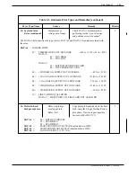
Страница 443: ...s information about How Adaptive Integration works Mitel SX 200 Digital requirements Mitel SX 200 Digital limitations Mitel SX 200 Digital configuration VP 300 configuration Installation and testing including an Installation Checklist Maintenance Mitel SX 200 Digital and Superset are registered trademarks of Mitel Corporation Toshiba VP Systems Release 6 1 February 1993 ...

Страница 444: ......

Страница 445: ...mber and the original called extension of external calls that have been forwarded to the VP 300 The calling and called extension numbers of internal calls that have been forwarded to the VP 300 The extension number of an internal station calling the VP 300 directly For many applications Personal Assistance and Auto Transfer to Assistance are recommended For details regarding these two features ref...

Страница 446: ...owing describes how the VP 300 uses call record information to identify and process various types of calls When phones are set to forward to the VP 300 on ring no answer RNA busy the VP 300 provides secondary answering for both internal and external calls The Mitel SX 200 Digital does not provide the VP 300 with the reason a call was forwarded so the VP 300 reports the status of all forwarded call...

Страница 447: ...box the VP 300 performs a screened transfer to the personal assistance position If that position does not answer or is busy the VP 300 prompts Personal assistance is unavailable Please leave a private message at the tone for name or dial zero for the operator It may be desired to direct some types of calls for example certain trunk calls and or calls to selected extensions immediately to personal ...

Страница 448: ...ded by the name recorded for the mailbox associated with the extension If a caller sends a Quick Message from a phone other than their own the message is preceded by the name recorded for that phone s mailbox When calling from any extension a caller may Enter their own mailbox by pressing followed by their mailbox number and password Call a network location by dialing the network access code and e...

Страница 449: ... contain the extension number in the name field the call is handled as a direct external call from Trunk Group 0 The VP 300 does not identify the source of the call If Trunk Group 0 is set up in the TRUNK GROUP Table the VP 300 answers with the greeting for Trunk Group 0 If Trunk Group 0 is not configured the VP 300 answers with the main company greeting If the attendant is the calling party of a ...

Страница 450: ...rt number 9109 020 000 may be available If so Superset lines from the analog line cards are recommended since they send display information more quickly than the digital COV line cards Part number 9109 012 XXX which supports various peripheral devices including the Superset 4 DN does not work with Mitel Adaptive Integration Cables One 25 pair cable per slot Software Requirements The following soft...

Страница 451: ...indication One or more Superset port from the PBX is required for message waiting control This port must be restricted so that it cannot answer calls Message waiting indication for a Superset 4 display telephone appears as a callback message The VP 300 cannot be called back from a Superset 4 because the MIC message waiting port cannot answer calls Message waiting indicators on a Superset 4 display...

Страница 452: ...on COV Voice Mail port message waiting indication does not require the MIC port to call a station in order to control its message waiting indicator Stations may use busy forward all forward or do not disturb without any conflict with VP message waiting indication If a station s message waiting indicator is activated by a COV voice mail port the SX 200 Digital automatically extinguishes the indicat...

Страница 453: ...ammed name or have a programmed name that includes the employee s mailbox number This is a requirement for each Superset 4 that will have full CPI functionality When all VP 300 ports are busy a call can forward on ring no answer to busy tone This is because these PBX software releases do not have a hunt group overflow or permit hunt group queuing for internal calls Generic 1003 A programmable name...

Страница 454: ... trunk number Prior to D96 7 if the trunk is not part of a trunk group or by trunk group number if the trunk is part of a trunk group Each trunk group that is to be identified by the VP 300 must be configured with either no name or with a name that includes the string TXXX XXX is the trunk group number or some other number that permits the VP 300 to identify the trunk group via the VP 300 TRUNK GR...

Страница 455: ... the VP 300 perform message waiting indication Recommendation Since the VP 300 cannot control a phone s message waiting indicator when that phone forwards on busy or all forward we recommend that phones using MWI be forwarded to the VP 300 only on ring no answer DID calls require coverage on busy therefore we do not recommend using MWI for extensions that receive DID calls Instead use the VP 300 r...

Страница 456: ... only on ring no answer Recommendation We recommend assigning two extensions to each hung group agent one extension in the hunt group not forwarded and the other a personal line forwarded to the VP 300 for call coverage This requires an additional port in the PBX for each agent If the agents do not have multiline phones this also requires additional phones Toshiba VP Systems Release 7 1 July 1994 ...

Страница 457: ... conventions for names that may be programmed in the SX 200 Digital Naming Conventions The Mitel SX 200 Digital permits assignment of alphanumeric names to trunk groups individual trunks and individual extensions This name may be up to eight characters for trunks or trunk groups and up to ten characters for an extension For correct operation of CPI some restrictions apply to how these names are de...

Страница 458: ...nning of name 9 T156 Number precedes trunk number MIC Extensions Each MIC port requires a Superset 4 extension from the Mitel PBX The MIC message waiting ports the ports that MWI uses for control of message waiting indicators are configured differently from the remaining MIC ports The configuration for these message waiting ports is outlined here 1 Allocate a Superset extension for each of the MIC...

Страница 459: ...et 4 Immediate Line Select 1003 and earlier Auto Outgoing Line Enable 1004 and later ENABLED Assign this class of service option only if using sub attendant message waiting indication 606 SUPERSET sub attendant ENABLED Assign this class of service option only if using COV Voice Mail port message waiting indication 229 COV Voice Mail Port ENABLED All other COS options must be disabled or set so tha...

Страница 460: ...ng Default 0 Assign this class of service option to the call processing port only if not using the COV Voice Mail port message waiting indication 229 COV Voice Mail Port ENABLED 604 SuperSet 4 Immediate Line Select 1003 and earlier Auto Outgoing Line Enable 1004 and later ENABLED Assign these options according to the VP 300 s requirements for inter trunk connections 313 CO Trunk to CO Trunk Connec...

Страница 461: ...ld be blank 6 CPI only Using CDE form 17 HUNT GROUPS Create a hunt group that includes all of the MIC port extensions used for call processing If this is an upgrade of an installed VP 300 use the existing VP 300 port hunt group but be sure to remove all of the old VP 300 port extensions from the hunt group Otherwise allocate a new hunt group Program the hunt group as follows ACCESS CODE Allocate a...

Страница 462: ... the VP 300 The Name entries for all such trunks should be blank Except for Generic 1000 which does not allow naming of trunk groups use CDE form 16 TRUNK GROUPS to check the names of any trunk groups containing trunks to be answered by the VP 300 Be sure that any names assigned to these trunk groups follow the naming conventions described in the beginning of this section Station Extensions Certai...

Страница 463: ...ng indicators must not be assigned COS option 77 Stations that are to have message waiting indicators controlled by the VP 300 must be connected to line cards in the Mitel SX 200 Digital that support message waiting lamps For Generic 1003 only stations that have been assigned a name in CDE form 09 STATION SUPERSET TELEPHONES must have the station extension number included in the name according to ...

Страница 464: ...S Attribute 9 to extensions having these indicators Do not assign COS Attribute 9 to extensions that do not have message waiting indicators Called Party Identification provides several mailbox convenience features for direct internal callers as described in Called Party Identification Call Processing in this section Every VP 300 mailbox may use all of these features except the Personal Greeting Ac...

Страница 465: ...ibute to distinguish these ports from the integrated MIC ports SLOTS Table ANSWERING MODE With Mitel SX 200 Digital Adaptive Integration all integrated ports should be configured for AX answering mode to maximize utilization of VP 300 ports CONFIGURATION OF PORTS To maximize system performance and port usage all VP 300 ports should be configured for OUTCALL except the ports used for message waitin...

Страница 466: ...connect to the VP 300 when it detects that a caller has hung up System Parameter 79 LAMP MW ON PRE EXTENSION DIGITS System Parameter 81 LAMP MW OFF PRE EXTENSION DIGITS If the VP System is using COV Voice Mail port message waiting indication modify both System Parameter 79 and System Parameter 81 to be 00 These parameter values tell the integration software to perform message waiting indication us...

Страница 467: ...arameters for Table different trunk groups by VP 300 COS Configure Trunk Group 0 with a greeting for use with internal forwarded calls received without extension numbers The greeting should specify that the person called does not have a mailbox on the system For all software release levels lower than Generic 1003 Called Party Identification identifies incoming trunks by their individual trunk numb...

Страница 468: ...ptive Integration Configuration of Test Extensions Configure two additional analog extensions in the Mitel SX 200 Digital before performing the tests described in the following sections The configuration procedure for these extensions is described below Toshiba VP Systems Release 7 1 July 1994 10 1 24 Installation and Maintenance Manual Table 10 1 1 Test Equipment 2500 type single line touchtone p...

Страница 469: ...ne of the analog test extensions Mitel SX 200 Digital Testing Perform the tests in this section before the actual installation of the MIC board For these tests disconnect all cables connecting the VP 300 ports to the Mitel SX 200 Digital This section refers to the parts of the Superset 4 telephone according to the following diagram Figure 10 1 1 Please refer to this diagram for the locations of pa...

Страница 470: ...date return to the display NO Determine the cause and correct the problem before continuing E Check the display for the FWD prompt located near the left edge of the Superset 4 display If the prompt is not ON proceed with step F If the prompt is ON the Toshiba VP Systems Release 7 1 July 1994 10 1 26 Installation and Maintenance Manual 1 2 3 4 5 6 7 8 9 0 mic on off speaker on off select features d...

Страница 471: ...ne telephone as phone A The following tests refer to the extension numbers of these phones as EXT B and EXT A respectively B Connect a Superset 4 to the extension assigned to the first MIC port of the VP 300 used for answering calls Do not use the MIC extension that is used for Message Waiting Indication C Connect phone A to extension EXT A Connect phone B to extension EXT B The message waiting in...

Страница 472: ...is the trunk number If the display does not contain this information determine the cause and correct the problem before continuing C Hang up phone A D Using phone A again dial the extension number of the Superset 4 E Look at the Superset 4 display The display should contain this information XXX is the extension of phone A If the display does not contain this information determine the cause and cor...

Страница 473: ... phone A If the display does not contain this information determine the cause and correct the problem before continuing G Press the EXIT softkey on the Superset 4 this should appear as softkey 1 The time and date should return to the display Hang up phone A Leave phone B set to forward to the Superset 4 on ring no answer External Call Forwarded on Busy H Re configure the test trunk line to ring di...

Страница 474: ...re continuing C After the number of rings configured for ring no answer forward in phone B s PBX COS does phone B stop ringing and the Superset start ringing NO Determine the cause and correct the problem before continuing D Answer the Superset Hang up the Superset and phone A 6 PBX FORWARD ALL CALLS TEST This test verifies that an extension can forward all calls to the VP 300 access number A Set ...

Страница 475: ...the MSG softkey Does the Superset 4 return dial tone Is the phone B message waiting indicator OFF NO Determine the cause and correct the problem before continuing G Hang up the Superset 4 Using phone A call the Superset 4 Does the PBX return reorder tone If not check that the COS for MWI has Option 235 ORIGINATE ONLY enabled Correct the problem before continuing H Hang up phone A 7B MWI Test With ...

Страница 476: ...t for the PBX to initialize the Superset 4 This may take as long as 30 seconds Once the set is initialized the display should show the time and date If the display does not show the time and date within 30 seconds of connecting the phone correct the problem before continuing If the display contains information other than the time and date lifting the Superset handset off hook and replacing it may ...

Страница 477: ...eted The MIC goes through a power ON routine which takes about 30 seconds When the routine is finished the MIC begins to download its program code from the VP 300 VCU While the MIC is downloading both the Red and Green LEDs are ON If the Red LED remains on after three minutes there is a problem Call Toshiba technical support Wait until program downloading is complete When it is complete the Green ...

Страница 478: ...ING THE VP 300 FOR TEST Before proceeding make the following changes to the VP 300 configuration These changes are temporary they are required only for testing A Add a VP 300 mailbox that has a mailbox number matching the extension number for phone B This mailbox is referred to as mailbox B B Assign these attributes to the COS for mailbox B Attribute 9 MESSAGE WAITING LAMP Message Waiting Indicati...

Страница 479: ...ease leave a private message at the tone NO Determine the cause and correct the problem before continuing E While still connected to the VP 300 enter the mailbox number for mailbox B this should match the extension number of phone B Does the VP 300 respond with the prompt Thank you Just a moment and does phone B start to ring again NO Determine the cause and correct the problem before continuing F...

Страница 480: ...he extension of the VP 300 hunt group Be sure that you reach the position specified for overflow in the VP 300 hunt group If not correct the problem before continuing C Hang up phone A D Cancel the VP 300 ports FWD state by entering at the prompt TE C 2 7 EXTERNAL TRUNK CALL TO THE VP 300 This test verifies that the VP 300 correctly processes calls from trunks that have been auto terminated to the...

Страница 481: ...swer phone B After the number of rings configured for ring no answer forward in phone B s PBX COS does the VP 300 respond with Extension EXT B is unavailable Please leave a private message at the tone NO Determine the cause and correct the problem before continuing E Dial 9 9 to exit from the VP 300 and hang up phone A 9 EXTERNAL CALL TO A BUSY EXTENSION This test verifies that the VP 300 correctl...

Страница 482: ...ed for each trunk group repeat steps A through D for each group 11A MESSAGE WAITING FOR SYSTEMS USING MESSAGE WAITING INDICATION This test verifies correct operation of message waiting indication A Set phone B to forward to the VP 300 on a busy condition by dialing the feature access code for Call Forwarding Busy followed by the VP 300 access number After setting forwarding for phone B leave phone...

Страница 483: ...B MESSAGE WAITING FOR SYSTEMS NOT USING MESSAGE WAITING INDICATION This test verifies correct operation of message waiting notification for systems not using Message Waiting Indication A Set phone B to forward to the VP 300 on a busy condition by dialing the feature access code for Call Forwarding Busy followed by the VP 300 access number After setting forwarding for phone B leave phone B off hook...

Страница 484: ...hone B 12 FORWARDED INTERNAL CALL FROM AN EXTENSION THAT DOES NOT HAVE THE EXTENSION NUMBER IN THE NAME FIELD This test verifies that the VP 300 correctly processes a call to an extension number in the name field A With the Superset 4 on hook press the PROGRAM softkey followed by the NAME softkey The alphanumeric display should give this prompt B Program the phone s name to be A by pressing 1 the ...

Страница 485: ...is TE INT x 1 2 where x is the slot number and 2 is the reset flag LIST INTEGRATION This command lists the current state of the MIC board the diagnostic L INT x 1 status the status of the links and the pegs The form of the command is L INT x 1 where x is the slot number An example listing is L INT 4 1 INTEGRATION STATUS CARD ID Mitel CARD STATUS UP DIAGNOSTIC OK LINK 1 STATUS ACTIVE LINK 2 STATUS ...

Страница 486: ...ation and Maintenance manual MAINTENANCE Hardware Errors Link 1 2 Status There are six possible states for the digit display set links to the MIC IDLE Link operating properly No call ACTIVE Link is handling a call MSG WAIT Link is performing message waiting indication DOWN Link is not receiving commands DEAD Link loop current is not detected Link is probably disconnected INIT MIC firmware is perfo...

Страница 487: ...ll come in at the same time 5 MSG WT ERROR Number of times the MIC detected an error while trying to control a message waiting indicator this does not include Message Waiting Not Configured or Message Waiting Not Able to Make 6 SOURCE ERROR Number of times the MIC firmware could not identify the source of a call 7 DEST ERROR Number of times the MIC firmware could not identify the destination of a ...

Страница 488: ...isplay 13 ANSWER ERROR Number of times the VCU went off hook before the firmware finished reading the display 15 DOWN ERROR Number of times the MIC firmware reported the link to be down 16 INT ERROR Miscellaneous firmware error has occurred For information on hardware errors regarding integrated systems refer to Installation and Maintenance manual MAINTENANCE Hardware Errors Toshiba VP Systems Rel...

Страница 489: ...0 MIC port Confirm the Mitel SX 200 Digital software level for release specific configuration issues The Mitel SX 200 Digital must have two unassigned COS available one for CPI and one for MWI Description Item 1 2 3 Complete Table 10 1 3 Mitel SX 200 Digital Configuration Before making any changes print out the database Verify and highlight areas where changes are required Configure the MIC Supers...

Страница 490: ...13 as follows TRANSFER INITIATE CODE FE RECONNECT CODE AFTER NO ANSWER F RECONNECT CODE AFTER BUSY F RECONNECT CODE AFTER FAST BUSY F TRANSFER COMPETE CODE NONE Modify System Parameter 16 as follows ALT TRANSFER INITIATE CODE FE ALT RECONNECT CODE AFTER NO ANSWER F ALT RECONNECT CODE AFTER BUSY F ALT RECONNECT CODE AFTER FAST BUSY F ALT TRANSFER COMPETE CODE NONE Modify System Parameter 33 to be N...

Страница 491: ...r outcall except the port used for MWI Description Item 15 16 17 18 Complete Command M SYS 131 M SYS 170 M SYS 191 M SLOT Table 10 1 5 After All Changes Have Been Made for MWI and CPI When you exit the UPDATE after making the necessary changes the VP 300 prompts FOR CHANGES TO TAKE EFFECT SYSTEM MUST BE RESTARTED Restart the system Description Item 1 2 Complete Command RESTA Table 10 1 6 Installat...

Страница 492: ...232C cable Hard copy of the VP 300 configuration database Hard copy of the PBX configuration Single line analog extensions connected to RJ11 jacks for testing Individually addressable trunk line into the PBX Mitel Superset 4 display phone This phone is required for testing purposes only It is used to emulate the MIC board Modular adapters for 2500 type and Superset 4 extensions Armiger AA2560A or ...

Страница 493: ...fect CPI 10 2 8 Applications 10 2 9 10 2 4 Mitel SX 100 SX 200 Analog Configuration 10 2 11 Naming Conventions 10 2 11 System Options 10 2 12 MIC Extensions 10 2 12 Trunks and Trunk Groups 10 2 14 Station Extensions 10 2 14 10 2 5 MP 300 Configuration 10 2 15 10 2 6 Mitel SX 100 SX 200 Analog Installation and Testing 10 2 19 Configuration of Test Extensions 10 2 19 Mitel SX 100 SX 200 Analog Testi...

Страница 494: ... 1 Test Equipment 10 2 19 10 2 2 Mitel SX 100 SX 200 Analog Requirements 10 2 39 10 2 3 Mitel SX 100 SX 200 Analog Configuration 10 2 39 10 2 4 VP 300 Configuration Changes for MWI and CPI 10 2 40 10 2 5 After All Changes Have Been Made for MWI and CPI 10 2 41 10 2 6 Installation and Testing 10 2 41 10 2 7 Test Equipment 10 2 42 Toshiba VP Systems Release 6 1 February 1993 ...
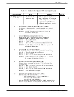
Страница 495: ...nformation about How Adaptive Integration works Mitel SX 100 SX 200 Analog requirements Mitel SX 100 SX 200 Analog limitations Mitel SX 100 SX 200 Analog configuration VP 300 configuration Installation and testing including an Installation Checklist Maintenance Mitel SX 100 SX 200 and Superset are registered trademarks of Mitel Corporation Toshiba VP Systems Release 6 1 February 1993 ...

Страница 496: ......

Страница 497: ...number and the original called extension of external calls that have been forwarded to the VP 300 The calling and called extension numbers of internal calls that have been forwarded to the VP 300 The extension number of an internal station calling the VP 300 directly For many applications Personal Assistance and Auto Transfer to Assistance are recommended For details regarding these two features r...

Страница 498: ...wing describes how the VP 300 uses call record information to identify and process various types of calls When phones are set to forward to the VP 300 on ring no answer RNA busy the VP 300 provides secondary answering for both internal and external calls The Mitel SX 100 SX 200 Analog does not provide the VP 300 with the reason a call was forwarded so the VP 300 reports the status of all forwarded...

Страница 499: ...ox the VP 300 performs a screened transfer to the personal assistance position If that position does not answer or is busy the VP 300 prompts Personal assistance is unavailable Please leave a private message at the tone for name or dial zero for the operator It may be desired to direct some types of calls for example certain trunk calls and or calls to selected extensions immediately to personal a...

Страница 500: ...y the name recorded for the mailbox associated with the extension If a caller sends a Quick Message from a phone other than their own the message is preceded by the name recorded for that phone s mailbox When calling from any extension a caller may Enter their own mailbox by pressing followed by their mailbox number and password Call a network location by dialing the network access code and extens...

Страница 501: ...ture If the called extension does not contain the extension number in the name field the call is handled as a direct external call from Trunk Group 0 The VP 300 does not identify the source of the call If Trunk Group 0 is set up in the TRUNK GROUP Table the VP 300 answers with the greeting for Trunk Group 0 If Trunk Group 0 is not configured the VP 300 answers with the main company greeting If the...

Страница 502: ...Extensions The Mitel SX 100 SX 200 Analog must provide a Superset 4 line for each MIC port in the VP 300 Cables One 25 pair cable per slot Software Requirements The following software is required for the Mitel SX 100 SX 200 Analog Release Generic 217 any revision level Options Required In Package None Configuration Requirements The Mitel SX 100 SX 200 Analog configuration must have two unassigned ...

Страница 503: ...any sub attendant turns the indicator OFF Once the VP 300 has turned ON a Superset 4 display telephone s message waiting indicator the Superset 4 periodically rings briefly to indicate that a message has been received The VP 300 must call a phone to control its message waiting indicator A phone may ring briefly while the VP 300 turns its indicator ON or OFF The VP 300 cannot control a phone s mess...

Страница 504: ...n characters long any revision can be programmed only at the phone itself not in the PBX configuration Each Superset 4 must either have no programmed name or have a programmed name that includes the mailbox number This is a requirement for each Superset 4 that will have full CPI functionality Members of hunt groups cannot have any type of forwarding on their phones without removing themselves from...

Страница 505: ...be forwarded to the VP 300 The customer has Superset 4 phones and 2500 type phones with message waiting lamps and the customer wants to have the VP 300 perform message waiting indication Recommendation Since the VP 300 cannot control a phone s message waiting indicator when that phone forwards on busy or all forward we recommend that phones using MWI be forwarded to the VP 300 only on ring no answ...

Страница 506: ...ken out of the hunt group even if the forwarding is only on ring no answer Recommendation We recommend assigning two extensions to each hunt group agent one extension in the hunt group not forwarded and the other a personal line forwarded to the VP 300 for call coverage This requires an additional port in the PBX for each agent If the agents do not have multiline phones this also requires addition...

Страница 507: ...Options MIC Extensions Trunks and Trunk Groups Station Extensions Prior to these sections is a description of the conventions for names that may be programmed for Superset phones Naming Conventions The Mitel SX 100 SX 200 Analog permits assignment of alphanumeric names to individual Superset extensions This name may be up to ten characters long For correct operation of CPI some rstrictions apply t...

Страница 508: ...RSET Sub Attendant MWI only 189 Flash Timer 0 7 seconds 276 Message Waiting Setup Lamp MWI only The Call Forwarding Don t Answer Time Out System Option 255 256 or 257 must be set longer than the length of time corresponding to the VP 300 INFORMATION Table Index 7 RINGS BEFORE NO ANSWER This ensures tha the VP 300 can still perform screened transfers to a ringing extension that has been forwarded o...

Страница 509: ...sole in extended programming mode to configure the MIC Superset extensions and proceed as follows MWI only Allocate a Superset extension to be used for controlling message waiting indicators Assign this extension the COS defined for MWI in step 2 above This extension cannot be used to answer calls Allocate the Superset extensions to be used for call processing Assign these extensions the COS defin...

Страница 510: ...led or disabled by mailbox holders by means of feature access codes at the station itself It is the responsibility of each individual to turn their forwarding ON or OFF as the application requires For extensions using MWI only the use of Call Forwardng Don t Answer is recommended because when a phone forwards immediately the VP 300 cannot turn that phone s message waiting indicator ON or OFF Refer...

Страница 511: ...rovides message waiting indication from Configuration the VP 300 for phones equipped with message waiting indicators Assign VP 300 COS Attribute 9 to extensions having these indicators Do not assign COS Attribute 9 to extensions that do not have message waiting indicators Called Party Identification provides several mailbox convenience features for direct internal callers as described in Called Pa...

Страница 512: ...t operate in a non integrated mode use this COS attribute to distinguish these ports from the integrated MIC ports SLOTS Table ANSWERING MODE With Mitel SX 100 SX 200 Analog Adaptive Integration all integrated ports should be configured for AX answering mode to maximize utilization of VP 300 ports CONFIGURATION OF PORTS To maximize system performance and port usage all VP 300 ports should be confi...

Страница 513: ...hen the port is forwarded removing the port from the hunt group When forwarding is cancelled the VP 300 puts the port back on hook so that it can answer calls System Parameter 77 PBX SUPPLIES MOMENTARY DISCONNECT Modify the value of System Parameter 77 to be YES Although the Mitel SX 100 SX 200 Analog does not actually provide momentary disconnect the MIC simulates the momentary disconnect to the ...

Страница 514: ...ause the PBX automatically cancels message waiting for Superset 4 display telephones after 24 hours System Parameter 191 is required System Parameter 191 reactivates the message waiting indicator every 24 hours TRUNK GROUP The TRUNK GROUP Table specifies call processing parameters for Table different trunk groups by VP 300 COS Configure Trunk Group 0 with a greeting for use with internal forwarded...

Страница 515: ... Integration Configuration of Test Extensions Configure two additional analog extensions in the Mitel SX 100 SX 200 Analog before performing the tests described in the following sections The configuration procedure for these extensions is described below Toshiba VP Systems Release 6 1 February 1993 MITEL SX 100 SX 200 ANALOG ADAPTIVE INTEGRATION 10 2 19 Table 10 2 1 Test Equipment 2500 type single...

Страница 516: ...e of the analog test extensions Mitel SX 100 SX 200 Analog Testing Perform the tests in this section before the actual installation of the MIC board For these tests disconnect all cables connecting the VP 300 ports to the Mitel SX 100 SX 200 Analog This section refers to the parts of the Superset 4 telephone according to the following diagram Please refer to this diagram for the locations of parts...

Страница 517: ...urn to the display NO Determine the cause and correct the problem before continuing E Check the display for the FWD prompt located near the left edge of the Superset 4 display If the prompt is not ON proceed with step F If the prompt is ON the Toshiba VP Systems Release 6 1 February 1993 MITEL SX 100 SX 200 ANALOG ADAPTIVE INTEGRATION 10 2 21 1 2 3 4 5 6 7 8 9 0 mic on off speaker on off select fe...

Страница 518: ...ine telephone as phone A The following tests refer to the extension numbers of these phones as EXT B and EXT A respectively B Connect a Superset 4 to the extension assigned to the first MIC port of the VP 300 used for answering calls Do not use the MIC extension that is used for Message Waiting Indication C Connect phone A to extension EXT A Connect phone B to extension EXT B The message waiting i...

Страница 519: ...runk number If the display does not contain this information determine the cause and correct the problem before continuing C Hang up phone A D Using phone A again dial the extension number of the Superset 4 E Look at the Superset 4 display The display should contain this information XXX is the extension of phone A If the display does not contain this information determine the cause and correct the...

Страница 520: ... information YYY is the extension number of phone A If the display does not contain this information determine the cause and correct the problem before continuing G Press the EXIT softkey on the Superset 4 this should appear as softkey 1 The time and date should return to the display Hang up phone A Leave phone B set to forward to the Superset 4 on ring no answer External Call Forwarded on Busy H ...

Страница 521: ...B is on hook B From phone A call the extension number of phone B Does phone B ring NO Determine the cause and correct the problem before continuing C After the duration specified by the PBX System Option for Call Forwarding Don t Answer Time out does phone B stop ringing and the Superset start ringing NO Determine the cause and correct the problem before continuing D Answer the Superset Hang up th...

Страница 522: ...he cause and correct the problem before continuing F Press the MSG softkey Does the Superset 4 return dial tone Is the phone B message waiting indicator OFF NO Determine the cause and correct the problem before continuing G Hang up the Superset 4 Using phone A call the Superset 4 Does the PBX return reorder tone If not check that the COS for MWI has Option 44 ORIGINATE ONLY enabled Correct the pro...

Страница 523: ... to indicate card status and are from top to bottom The installation procedure refers to the LEDs by the above names After the PBX tests have been successfully completed and the VP 300 ports reconnected to the PBX proceed with the installation of the MIC using the following procedure 1 Forward the VP 300 port extensions by entering at the prompt TE C 1 2 Remove any VP 300 line cards that are to be...

Страница 524: ...ted to the correct VP 300 ports A On the VP 300 terminal enter L T and select 1 ALL ACTIVITIES and C for continuous display B From phone A call the extension of the VP 300 port 1 Does the VP 300 answer with To enter your mailbox press pound NO Determine the cause and correct the problem before continuing If the system activity trace does not show that the correct port answered change the port conn...

Страница 525: ...e VP 300 access number After setting forwarding for phone B make sure phone B is on hook B From phone A call phone B Does phone B start to ring NO Determine the cause and correct the problem before continuing C Do not answer phone B After the duration specified by the PBX System Option for Call Forwarding Don t Answer Time out does phone B stop ringing NO Determine the cause and correct the proble...

Страница 526: ...and phone B 6 EXTERNAL TRUNK CALL TO THE VP 300 This test verifies that the VP 300 correctly processes calls from trunks that have been auto terminated to the VP 300 hunt group Be sure to test all such trunk groups 1 800 InWATS lines can be tested individually even if they are bands from other areas by using plant test numbers Get these numbers from the CO if you do not already know them A From ph...

Страница 527: ...t the tone NO Determine the cause and correct the problem before continuing E Dial 9 9 to exit from the VP 300 and hang up phone A 8 EXTERNAL CALL TO A BUSY EXTENSION This test verifies that the VP 300 correctly processes an external call that reaches a busy extension A Set phone B to forward to the VP 300 on a busy condition by dialing the feature access code for Call Forwarding Busy followed by ...

Страница 528: ... a busy condition by dialing the feature access code for Call Forwarding Busy followed by the VP 300 access number After setting forwarding for phone B leave phone B off hook so that it appears busy B From phone A call out and back in on a trunk auto terminated to the VP 300 C Does the VP 300 answer properly NO Determine the cause and correct the problem before continuing If the VP 300 is equipped...

Страница 529: ...e B leave phone B off hook so that it appears busy B From phone A call out and back in on a trunk that auto terminates to the VP 300 C Does the VP 300 answer properly NO Determine the cause and correct the problem before continuing If the VP 300 is equipped with IntraMessaging you may prefer to use the Quick Message feature to leave a message for phone B instead of following the instructions of st...

Страница 530: ...name field A With the Superset 4 on hook press the PROGRAM softkey followed by the NAME softkey The alphanumeric display should give this prompt B Program the phone s name to be A by pressing 1 the NEXT softkey and then the SAVE softkey C Now press the PROGRAM softkey again followed by the CALL FWD softkey D Use the softkey prompts and alphanumeric display to set up ALWAYS FORWARD call forwarding ...

Страница 531: ... flag LIST INTEGRATION This command lists the current state of the MIC board the diagnostic L INT x 1 status the status of the links and the pegs The form of the command is L INT x 1 where x is the slot number An example listing is CLEAR This command clears the MIC pegs The form of the command is INTEGRATION C INT x 1 C INT x 1 where x is the slot number L INT 4 1 INTEGRATION STATUS CARD ID Mitel ...

Страница 532: ... 2 Status There are six possible states for the digit display set links to the MIC IDLE Link operating properly No call ACTIVE Link is handling a call MSG WAIT Link is performing message waiting indication DOWN Link is not receiving commands DEAD Link loop current is not detected Link is probably disconnected INIT MIC firmware is performing link initialization Only the DOWN and DEAD states are err...

Страница 533: ...ome in at the same time 5 MSG WT ERROR Number of times the MIC detected an error while trying to control a message waiting indicator this does not include Message Waiting Not Configured or Message Waiting Not Able to Make 6 SOURCE ERROR Number of times the MIC firmware could not identify the source of a call 7 DEST ERROR Number of times the MIC firmware could not identify the destination of a forw...

Страница 534: ...he MIC firmware reported the link to be down 16 INT ERROR Miscellaneous firmware error has occurred For information on hardware errors regarding integrated systems refer to Installation and Maintenance manual MAINTENANCE Hardware Errors This section offers a checklist of issues relating to the VP 300 and the Mitel SX 100 SX 200 Analog The list is presented in the order that the installation proces...

Страница 535: ...for CPI and one for MWI Description Item 1 2 Complete Table 10 2 3 Mitel SX 100 SX 200 Analog Configuration Before making any changes print out the database Verify and highlight areas where changes are required Configure the MIC Superset extension used for MWI Configure the MIC Superset extension used for CPI Configure trunks that will be answered by the VP 300 Configure individual station extensi...

Страница 536: ... their mailboxes Assign COS Attribute 58 to non integrated ports Modify System Parameter 13 as follows TRANSFER INITIATE CODE FE RECONNECT CODE AFTER NO ANSWER F RECONNECT CODE AFTER BUSY F RECONNECT CODE AFTER FAST BUSY F TRANSFER COMPETE CODE NONE Modify System Parameter 16 as follows ALT TRANSFER INITIATE CODE FE ALT RECONNECT CODE AFTER NO ANSWER F ALT RECONNECT CODE AFTER BUSY F ALT RECONNECT...

Страница 537: ...all ports are configured for outcall except the port used for MWI Description Item 14 15 16 17 18 19 Complete Command M SYS 116 M SYS 117 M SYS 131 M SYS 170 M SYS 191 M SLOT Table 10 2 5 After All Changes Have Been Made for MWI and CPI When you exit the UPDATE after making the necessary changes the VP 300 prompts FOR CHANGES TO TAKE EFFECT SYSTEM MUST BE RESTARTED Restart the system Description I...

Страница 538: ... RS 232C cable Hard copy of the VP 300 configuration database Hard copy of the PBX configuration Single line analog extensions connected to RJ11 jacks for testing Individually addressable trunk line into the PBX Mitel Superset 4 display phone This phone is required for testing purposes only It is used to emulate the MIC board Modular adapters for 2500 type and Superset 4 extensions Armiger AA2560A...

Страница 539: ...tel SX 2000 Configuration 10 3 14 Naming Conventions 10 3 14 MIC Extensions 10 3 16 Trunks and Trunk Groups 10 3 18 Call Rerouting 10 3 19 Station Extensions 10 3 20 10 3 5 VP 300 Configuration 10 3 21 External Call Configuration 10 3 21 Internal Call Configuration 10 3 21 Changes for Called Party Identification 10 3 21 Changes for Message Waiting Notification 10 3 24 10 3 6 Mitel SX 2000 Installa...

Страница 540: ...ample 10 3 6 10 3 4 Call Rerouting Assignment Example Entries 10 3 6 10 3 5 Diagram of the Superset 4 Telephone 10 3 28 Table Description Page 10 3 1 Test Equipment 10 3 26 10 3 2 Mitel SX 2000 Requirements 10 3 51 10 3 3 Mitel SX 2000 Configuration 10 3 51 10 3 4 VP 300 Configuration Changes for MWI and CPI 10 3 52 10 3 5 After All VP 300 Changes are Complete 10 3 53 10 3 6 Installation and Testi...

Страница 541: ...ation about How Adaptive Integration works Mitel SX 2000 requirements Mitel SX 2000 limitations Mitel SX 2000 configuration VP 300 configuration Installation and testing including an Installation Checklist Maintenance Mitel SX 2000 SX 2000 S and SX 2000 SG and Superset are registered trademarks of Mitel Corporation Toshiba VP Systems Release 6 1 February 1993 ...

Страница 542: ......

Страница 543: ...e VP 300 directly For many applications Personal Assistance and Auto Transfer to Assistance are recommended For details regarding these two features refer to the Feature Description manual CUSTOMIZATION Personal Assistance Personal Assistance operates in conjunction with Called Party Identification in integrated systems This chapter is written solely for the Mitel SX 2000 S and SX 2000 SG PBXs Do ...

Страница 544: ...MWI for a specified group of VP 300 COS This configuration requires Adaptive Integration MWI on any MIC port If the SX 2000 has software level H10 9 or later all MIC ports can be assigned the PBX class of service option COV Voice Mail Port so that any VP 300 MIC outcall port can perform MWI This configuration requires Adaptive Integration MWI on any port If the SX 2000 has software level H10 15B o...

Страница 545: ...der different conditions Using the SX 2000 Station Call Forwarding a station can redirect calls to a specified answer point under any of the following conditions Called extension is busy or in DND Do Not Disturb and the call source is internal Called extension is busy or in DND and call source is external Called extension doesn t answer and the call source is internal Called extension doesn t answ...

Страница 546: ...able also assigns the type of Do Not Disturb to be used for each directory number Do Not Disturb may be selected for internal calls only for external calls only or for all calls including calls from an attendant Calls reroute to an alternative answer point immediately if the preferred answer point is busy or in DND but Call Rerouting on ring no answer is governed by two timers The Call Forward No ...

Страница 547: ...e answer point is the VP 300 The Second Alternative answer point in the event the VP 300 fails to answer the call is the attendant Toshiba VP Systems Release 6 1 February 1993 MITEL SX 2000 ADAPTIVE INTEGRATION 10 3 5 Figure 10 3 1 Call Rerouting First Alternative Assignment Example CALL REROUTING FIRST ALTERNATIVE ASSIGNMENT Busy DND Originating Device First Alternative Number Directory Number Ro...

Страница 548: ...directory number 3376 Toshiba VP Systems Release 6 1 February 1993 10 3 6 Installation and Maintenance Manual Figure 10 3 3 Call Rerouting Always Alternative Assignment Example CALL REROUTING ALWAYS ALTERNATIVE ASSIGNMENT Always Originating Device Always Alternative Number Directory Number Routed To DID TIE CO INTERNAL No Reroute No Reroute No Reroute No Reroute AA 1 Reroute No Reroute Reroute No ...

Страница 549: ...nes connected to the MIC This section describes how the VP 300 uses call record information to identify and process various types of calls Direct Calls from Mitel SX 2000 trunks can be directed to the VP 300 for answering External Trunks through the Mitel SX 2000 s trunk configuration Refer to the SX 2000 Configuration section Trunks and Trunk Groups for the requirements to configure trunks For ca...

Страница 550: ...BX then provides a display containing the following information XXX is the trunk number that the VP 300 uses to identify trunk groups Upon receiving the forwarded call the VP 300 prompts the caller with the status of the extension or with the extension s greeting if it is ON followed by Please leave a private message at the tone dial another number or dial zero for personal assistance If the calle...

Страница 551: ...enience features are available for extensions associated with single mailboxes To take advantage of these features a caller must be calling the VP 300 directly from their own extension The VP 300 already knows the mailbox associated with each extension so the caller may Press to enter the mailbox without entering the mailbox number The VP 300 asks for the mailbox password Press 0 to turn ON OFF or...

Страница 552: ...r is attached to the caller s message so the VP 300 knows which caller left the message When the person receiving the message listens to it the VP 300 is able to play the name of the caller who left the message before playing the message itself The person receiving the message may automatically reply to it or immediately call the sender IntraMessaging feature If the called extension has a telephon...

Страница 553: ... release Prior to H10 9E the PBX class of service option COV Voice Mail Port is not available This option is required to avoid certain MWI and CPI limitations If the PBX is using MSDN Mitel Switched Digital Network software the PBX software level must be H10 15 or later to avoid some CPI limitations Refer to Mitel SX 2000 Limitations in this chapter for details Options Required In Package None Con...

Страница 554: ... so that when employees attempt to call the message waiting port they are redirected to VP 300 hunt group Employees can then use the Superset 4 s CALL softkey to call the VP 300 upon reading the message The dedicated message waiting control ports must have their own PBX Class of Service without the COV Voice Mail Port Class of Service option If the message waiting control ports have the COV Voice ...

Страница 555: ... for calls from other nodes to local extensions The COV Voice Mail Port class of service option should not be used for the VP 300 ports in a multinode SX 2000 installation unless the SX 2000 PBX has software level H10 15 or later For multinode SX 2000 installations using MSDN the PBX does not provide the MIC with correct call information for calls which forward across MSDN links Do not reroute or ...

Страница 556: ...e Assignment System Options Assignment Superset 4 Assignment Superset 4 Key Assignment Telephone Directory Trunk Assignment Trunk Service Assignment Interconnect Restriction Table Intercept Handling Assignment The changes to the PBX configuration are divided into four sections MIC Extensions Trunk and Trunk Groups Rerouting Assignment Station Extensions Prior to these sections is a description of ...

Страница 557: ...ing the LASTNAME FIRSTNAME format the LASTNAME must be preceded by the extension number Programming names in this manner will interfere with proper operation of the Dial By Name feature unless non prime names that do not include the extension number are assigned for each extension Names for trunk service numbers must start with the string TXXX where XXX is the trunk service number This number excl...

Страница 558: ...Yes Call Forwarding Accept Yes Call Forwarding Internal Destination Yes Camp on Tone Security Yes COV Voice Mail Port if option is available Yes Do No Disturb Yes Message Waiting Yes Message Waiting Inquire Yes Auto Camp on Timer 30 seconds Busy Tone Timer 30 seconds Call Forward No Answer Timer 20 seconds Dialing Conflict Timer 2 seconds First Digit Timer 15 seconds Inter digit Timer 4 seconds Lo...

Страница 559: ...Day Night 1 and Night 2 operation Class of Restriction and Default Account Code Index Assign these parameters according to the customer application 6 Access the Hunt Group Assignment form to create a hunt group that includes all of the MIC port extensions used for CPI If this is an upgrade of an installed VP 300 system use the existing VP 300 port hunt group but include only the CPI extensions as ...

Страница 560: ... Access the Station Service Assignment form to assign station service parameters to each MWI extension Program the form s entries as follows Intercept Number Assign Intercept Handling number selected in step 11 above Class of Service Assign the COS number allocated for the MWI ports in step 8 above Use the same COS for Day Night 1 and Night 2 operation Class of Restriction and Default Account Code...

Страница 561: ...d No Answer Timer an SX 2000 COS option but shorter than the sum of any two values for the Call Forward No Answer timer Refer to the Operation of Mitel SX 2000 Adaptive Integration section Call Rerouting Proceed with the Call Rerouting configuration using the following procedure 1 List all Call Rerouting First Alternative Assignments and Call Rerouting Second Alternative Assignments and note which...

Страница 562: ...h user s PBX class of service is set to a time interval longer than the number of rings specified in the VP 300 INFORMATION Table options Rings Before No Answer and Message Waiting Rings Configuration for Message Waiting Indication To ensure that the VP 300 can control message waiting indicators on single line stations be sure that those stations with lamps are assigned an appropriate ONS OPS Circ...

Страница 563: ...refore require entries for individual trunk numbers trunk service numbers or both depending upon the call processing application Entries in the TRUNK GROUP Table must not include leading zeroes because the VP 300 ignores leading zeros of trunk numbers and trunk service numbers Internal Call Configuration Called Party Identification provides several mailbox convenience features for direct internal ...

Страница 564: ...SX 2000 Adaptive Integration all integrated ports should be configured for AX answering mode to maximize utilization of VP 300 ports CONFIGURATION OF PORTS Set port testing to YES for all MIC ports To maximize system performance and port usage all the VP 300 call processing ports should be configured for outcall System Parameters System Parameter 13 TRANSFER INITIATE CODE RECONNECT CODE AFTER NO A...

Страница 565: ...VP 300 when it detects that a caller has hung up System Parameter 85 RECONNECT CODE AFTER 3RD PARTY HUNG UP Modify the value of System Parameter 85 to be F System Parameter 106 PORT FOR LAMP MESSAGE WAITING If a single VP 300 port is to be dedicated for MWI enter the port number in System Parameter 106 Otherwise modify System Parameter 106 to 0 System Parameter 116 INTEGRATION TYPE Modify the valu...

Страница 566: ...s class of service option is not available or cannot be used one or more VP 300 ports must be dedicated for message waiting control and cannot answer calls To enable the VP 300 to control message waiting indicators make the following configuration changes using the UPDATE program Mailbox COS COS Attribute 9 LAMP OR DISPLAY PHONE MESSAGE WAITING Assign a COS with Attribute 9 to those mailboxes of e...

Страница 567: ...hat the VP 300 checks for dial tone after attempting to deactivate a message waiting indicator If the PBX does not provide dial tone the message waiting deactivate was not successful System Parameter 170 INTEGRATION LAMP ON OFF LINK MUST MATCH For SX 2000 systems using multiple dedicated MIC MWI ports modify the value of System Parameter 170 to be YES System Parameter 191 HOUR TO REACTIVATE MSG WT...

Страница 568: ...rder 1 Configuration of test extensions 2 Testing of Mitel SX 2000 3 Installation of MIC board 4 Testing Adaptive Integration Toshiba VP Systems Release 6 1 February 1993 10 3 26 Installation and Maintenance Manual Table 10 3 1 Test Equipment 2500 type single line touchtone phones one with a message waiting indicator Terminal teleprinter directly connected to VP 300 Port J1 or SP1 via RS 232C cabl...

Страница 569: ...oint is the first MIC port in the VP 300 hunt group for all types of calling devices on both Busy DND and No Answer The Second Alternative answer point is the second analog extension for all types of calling devices Set up a Call Rerouting Always Alternative that reroutes to the first MIC port in the VP 300 hunt group for all types of calling devices but do not assign this Always Alternative to ei...

Страница 570: ... extensions used for the MIC links A Disconnect the 25 pair cables from the back of the VP 300 Toshiba VP Systems Release 6 1 February 1993 10 3 28 Installation and Maintenance Manual 1 2 3 4 5 6 7 8 9 0 mic on off speaker on off select features display hold 3 08 9 JAN 92 Program MSG Volume controls for speaker and ringer Prime Line key Softkeys numbered 1 to 6 starting from the left Figure 10 3 5...

Страница 571: ...nd do the time and date return to the display NO Determine the cause and correct the problem before continuing G Check the display for the FWD prompt located near the left edge of the Superset 4 display If the prompt is not ON proceed with step H If the prompt is ON the Superset 4 has some type of forwarding turned ON Turn the forwarding OFF as follows 1 Press the select features button 2 Press 1 ...

Страница 572: ...erify the circuit quality If the quality is bad determine the cause and correct the problem G Press the TRANS CONF softkey this should appear as softkey 3 to initiate a transfer If the softkey does not appear the Superset extension may be configured incorrectly in the PBX configuration Correct the problem before continuing H Check for stutter or solid dial tone after pressing the softkey and check...

Страница 573: ...ve that reroutes to the first MIC port in Day Night 1 and Night 2 operation Make sure phone B is on hook B Using phone A call the extension of phone B Dos the Superset 4 start to ring NO Determine the cause and correct the problem before continuing C Answer the Superset Hang up the Superset and phone A Change the Call Rerouting Always Alternative assignments for phone B s extension back to their p...

Страница 574: ...e trunk that terminates at the Superset 4 B Look at the Superset 4 display The display should contain this information If the display does not contain this information determine the cause and correct the problem before continuing C Hang up phone A D Using phone A again dial the extension number of the Superset 4 E Look at the Superset 4 display The display should contain this information XXX is th...

Страница 575: ...on YYY is the extension number of phone A If the display does not contain this information determine the cause and correct the problem before continuing G Press the EXIT softkey on the Superset 4 this should appear as softkey 1 The time and date should return to the display Hang up phone A External Call Forwarded on Ring No Answer H Reconfigure the test trunk line to ring directly into the extensi...

Страница 576: ...arded on Busy A Take phone B off hook to make it appear busy B Using phone A call the extension of phone B Does the call forward to the Superset 4 NO Correct the problem before continuing C Look at the display of the Superset 4 The display should contain this information XXX is the extension of phone B If the display does not contain this information determine the cause and correct the problem bef...

Страница 577: ... line key The display should contain this information XXX is the trunk number If the display does not contain this information determine the cause and correct the problem before continuing L Press the EXIT softkey on the Superset 4 Hang up phone A and phone B 10 DISPLAY TEST FOR CALLS FORWARDED ON ALWAYS REROUTE This test verifies that the MIC ports receive the proper display information from the ...

Страница 578: ...ct the problem before continuing F Press the EXIT softkey on the Superset 4 Hang up phone A External Call Forwarded on Always Reroute G Using phone A call out of the PBX and back in on the test trunk Does the call forward to the Superset 4 NO Determine the cause and correct the problem before continuing H Look at the Superset 4 display The display should contain this information XXX is the extensi...

Страница 579: ...e Superset handset off hook and replacing it may correct the problem C From phone A call the extension number of the Superset D Answer the Superset Transfer phone A to the attendant by pressing the TRANS CONF softkey dialing 0 and pressing the HANG UP softkey Does phone A get connected to the attendant NO Determine the cause and correct the problem before continuing E Connect the Superset to the 2...

Страница 580: ...g is complete When it is complete the Green LED is ON and the Red LED is OFF The MIC is not fully operational until after system port initialization is complete and the CPU has downloaded additional parameters to the card The four port LEDs on the MIC provide simple visual indication of port status The MIC port LEDs always remain OFF while a MIC port is disconnected or while the MIC firmware is in...

Страница 581: ... the correct port called change the lines so that the correct port answers C Repeat step B for each port 2 CONFIGURING THE VP 300 FOR TEST Before proceeding make the following changes to the VP 300 configuration These changes are temporary they are required only for testing A Add a VP 300 mailbox that has a mailbox number matching the extension number for phone B This mailbox is referred to as mai...

Страница 582: ...is unavailable Please leave a private message at the tone NO Determine the cause and correct the problem before continuing E While still connected to the VP 300 enter the mailbox number for mailbox B this should match the extension number of phone B Does the VP 300 respond with the prompt Thank you Just a moment and does phone B start to ring again NO Determine the cause and correct the problem be...

Страница 583: ...inates to the VP 300 Does the VP 300 answer with the greeting configured for the trunk NO Determine the cause and correct the problem before continuing B From the terminal connected to the VP 300 enter the PS command Does the port that answered show FWD state NO Determine the cause and correct the problem before continuing C Dial 9 9 to exit the VP 300 From the VP 300 terminal busy out the VP 300 ...

Страница 584: ...00 respond with the prompt Thank you Just a moment NO Determine the cause and correct the problem before continuing D After a short interval does the VP 300 respond with Extension EXT B is unavailable Please leave a private message at the tone NO Determine the cause and correct the problem before continuing E Dial 9 9 to exit from the VP 300 and hang up phone A 9 INTERNAL CALL TO AN EXTENSION ALWA...

Страница 585: ...termine the cause and correct the problem before continuing C After a short interval does the VP 300 respond with the prompt Extension EXT B is unavailable Please leave a private message at the tone NO Determine the cause and correct the problem before continuing D While still connected to the VP 300 enter the mailbox number of mailbox B Note that this should be the same as the extension number of...

Страница 586: ...ped with IntraMessaging you may prefer to use the Quick Message feature to leave a message for phone B instead of following the instructions of step D and step E D Dial the xtension number of phone B After the duration specified by the PBX System Option for Call Forwarding Don t Answer Time out the VP 300 should respond with Extension EXT B is busy Please leave a private message at the tone dial a...

Страница 587: ...g If the VP 300 is equipped with IntraMessaging you may prefer to use the Quick Message feature to leave a message for phone B instead of following the instructions of step D and step E D Dial the extension number of phone B After the duration specified by the PBX System Option for Call Forwarding Don t Answer Time out the VP 300 should respond Extension EXT B is in use Please leave a private mess...

Страница 588: ...ice option A In the PBX configuration access the telephone directory form Program phone B s name to be TEST B Save and confirm the change B Forward phone B to the VP 300 by going off hook and dialing the feature access code for Call Forward Follow Me followed by the extension number of the VP 300 hunt group C From phone A call phone B Does the VP 300 answer with the greeting for Trunk Group 0 NO D...

Страница 589: ...E INT x 1 2 where x is the slot number and 2 is the reset flag LIST INTEGRATION This command lists the current state of the MIC board the diagnostic L INT x 1 status the status of the links and the pegs The form of the command is L INT x 1 where x is the slot number An example listing is L INT X INTEGRATION STATUS CARD ID Mitel CARD STATUS UP DIAGNOSTIC OK LINK 1 STATUS ACTIVE LINK 2 STATUS IDLE L...

Страница 590: ...ns refer to the Installation and Maintenance manual MAINTENANCE Hardware Errors Link 1 2 Status There are six possible states for the digit display set links to the MIC IDLE Link operating properly No call ACTIVE Link is handling a call or doing message waiting indication MSG WAIT Link is performing message waiting notification DOWN Link is connected but is not receiving data from the PBX DEAD No ...

Страница 591: ...E COUNT Number of times that the VP 300 went off hook on this port to make an outcall and the MIC firmware saw a call come in at the same time 5 MSG WT ERROR Number of times the MIC detected an error while trying to control a message waiting indicator This does not include Message Waiting Not Configured or Message Waiting Not Able to Make 6 SOURCE ERROR Number of times the MIC firmware could not i...

Страница 592: ...gnizable display 13 ANSWER ERROR Number of times the VCU went off hook before the firmware finished reading the display 15 DOWN ERROR Number of times the MIC link was down 16 INT ERROR Miscellaneous firmware error has occurred For information on hardware errors regarding integrated systems refer to Installation and Maintenance manual MAINTENANCE Hardware Errors Toshiba VP Systems Release 6 1 Febru...

Страница 593: ...nfirm the SX 2000 software level for release specific configuration issues The Mitel SX 2000 must have two unassigned COS available one for CPI and one for message waiting indicator control Description Item 1 2 3 Complete Table 10 3 3 Mitel SX 2000 Configuration Before making any changes print out the database Verify and highlight areas where changes are required Configure the MIC Superset extensi...

Страница 594: ...ODE FE RECONNECT CODE AFTER NO ANSWER F RECONNECT CODE AFTER BUSY F RECONNECT CODE AFTER FAST BUSY F TRANSFER COMPLETE CODE NONE Modify System Parameter 16 ALTERNATE TRANSFER INITIATE CODE ALTERNATE RECONNECT CODE AFTER NO ANSWER ALTERNATE RECONNECT CODE AFTER BUSY ALTERNATE RECONNECT CODE AFTER FAST BUSY ALTERNATE TRANSFER COMPLETE CODE If alternate transfer codes are required configure them acco...

Страница 595: ...rs Modify the SLOTS Table so that all integrated ports are in AX mode and that all ports are configured for outcall except the port used for MWI Set testing to NO for all ports Description Item 15 16 17 18 19 20 21 22 Complete Command M SYS 85 M SYS 106 M SYS 116 M SYS 117 M SYS 131 M SYS 170 M SYS 191 M SLOT Table 10 3 5 After All VP 300 Configuration Changes Are Complete When you exit the UPDATE...

Страница 596: ...rinter directly connected to VP 300 PORT A via RS 232C cable Hard copy of the VP 300 configuration database Hard copy of the PBX configuration Single line analog extensions connected to RJ11 jacks for testing Individually addressable trunk line into the PBX Mitel Superset 4 display phone This phone is required for testing purposes only It is used to emulate the MIC board Description Quantity 2 1 1...

Страница 597: ...ns for Trunk Operation 11 14 Figures Figure Description Page 11 1 Central Office DID Application with Standard PBX Interface 11 3 11 2 PBX Application for Trunk Port Connection Employs PBX Trunk to Trunk Transfer 11 4 11 3 DAC Loop Ground Start Switch Locations 11 8 11 4 DAC I O Panel 11 9 11 5 VP 300 DAC I O Panel Mounting 11 11 Tables Table Description Page 11 1 SLOTS Table Configuration Changes...

Страница 598: ...Toshiba VP Systems Release 6 1 February 1993 ...
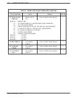
Страница 599: ... type of service where applications requiring the DAC are anticipated This chapter is intended to be used for the service and installation of the VP Direct Access Card with a VP 300 and is written for those field technicians who will be installing or servicing a DAC in conjunction with a VP 300 Included in this chapter are the following sections FCC Notice to the users DAC Overview Installation ...

Страница 600: ...Toshiba VP Systems Release 6 1 February 1993 ...

Страница 601: ...he user If a problem is found in premises wiring not telco installed you are subject to a service charge If a fault is in telco installed wiring you may be subject to a service call charge 4 Unless otherwise noted in the User s Manual e g fuses etc user may not under any circumstances in or out of warranty attempt any service adjustments or repairs on this unit It must be returned to the factory f...

Страница 602: ...start PBX trunks Configurable for DTMF or rotary address recognition DAC Application Considerations The use of the DAC is restricted to applications where the callers are never required to be transferred out of the VP 300 This card does not provide any call processing functionality The following considerations should be addressed when using the DAC The serving switching system must be capable of s...

Страница 603: ...ads of the DID trunk normally used to signal a DID extension The digits are used as a mailbox number and the call is answered with a personal greeting Toshiba VP Systems Release 6 1 February 1993 DAC INSTALLATION 11 3 Figure 11 1 Central Office DID Application with Standard PBX Interface VP 300 DAC I O Panel PBX CO Demarcation Loop Start Ground Start or additional DID trunks DAC Interface s Statio...

Страница 604: ...ers on incoming trunks to be transferred to outgoing PBX trunks without requiring that the transferring party remain on the line trunk to trunk transfer The PBX must send the called extension station number in DTMF signal over the outgoing trunk in band signaling The outgoing trunk is connected to a DAC port This application is also supported by standard line interface cards LICs when ports are pr...

Страница 605: ...er feed Do not connect the DAC I O panel to slot A12 Testing and enabling trunks Trunks DID or special service trunks must be ordered from the local telephone company or service provider These trunks should be installed up to the demarcation point by the telephone company or service provider The wiring from the demarcation point to the DAC I O panel and the VP 300 should only be performed by servi...

Страница 606: ...the UPDATE program to ADD a slot to the SLOTS Table If you are modifying a slot to accept the DAC use the MODIFY command Toshiba VP Systems Release 6 1 February 1993 11 6 Installation and Maintenance Manual Table 11 1 SLOTS Table Configuration Changes Information Required Possible Responses Connected to the port 1 8 digits For DX ports this may be any 1 8 digit reference number or NONE The COS sho...

Страница 607: ... operation may be desired In this case both the outgoing PBX trunk and the corresponding DAC port should be specified as ground start Two of the four DAC loop start ground start switches are shown in Figure 11 3 Both switches are shown in the loop start position Toshiba VP Systems Release 6 1 February 1993 DAC INSTALLATION 11 7 A SLOT Enter SLOT NUMBER to ADD Enter empty line when done ADD 1 6 LIC...

Страница 608: ...allations in USA and Canada only In other countries the power supply is provided by the local distributor Toshiba VP Systems Release 6 1 February 1993 11 8 Installation and Maintenance Manual Figure 11 3 DAC Loop Ground Start Switch Locations A B C D E F G H J K CHAN 3 CHAN 4 Port 4 Port 3 D204 U402 U403 U404 C404 RY4 R412 R413 TS4 L G R301 R302 C301 U302 U303 R311 R313 RY3 R312 LOOP GRND F302 C20...

Страница 609: ...nnection at the telephony ground point may require one or more special clamps This is determined on a site by site basis Install DAC Cards Plug the DAC into the VP 300 cabinet Since the DAC is hot pluggable the VP 300 need not be powered OFF to do this Verify that the cards are plugged into those slots configured for the DAC as described previously Up to eleven DAC cards may be installed in a VP 3...

Страница 610: ...ssary for the remaining slots Install cables only to slots containing DAC cards Do not install a cable to slot A12 4 Plug the DC power cable from the power supply into the 48 VDC connector on the DAC I O panel Switching the system power OFF at the PSU inside the cabinet does not turn OFF the DAC power supply The DAC power supply input power cord must be unplugged to turn it OFF CAUTION This unit h...

Страница 611: ...quivalent mounted on the backboard Cross connect the trunks to the 66M block or equivalent Refer to Table 11 2 for connections The DAC I O panel has a male amphenol connector therefore the cable must have a female amphenol connector When installing the wiring pay careful attention to the tip ring connections since reversal of these two leads on a port adversely affects the operation of DID trunks ...

Страница 612: ...O Panel DP EXT Connections DP EXT PIN NUMBER SIGNAL FUNCTION DP EXT PIN NUMBER SIGNAL FUNCTION 1 2 3 4 5 6 7 8 9 10 11 12 13 14 15 16 17 18 19 20 21 22 23 24 25 26 27 28 29 30 31 32 33 34 35 36 37 38 39 40 41 42 43 44 45 46 47 48 49 50 1RING1 1RING2 1RING3 1RING4 2RING1 2RING2 2RING3 2RING4 3RING1 3RING2 3RING3 3RING4 4RING1 4RING2 4RING3 4RING4 1TIP1 1TIP2 1TIP3 1TIP4 2TIP1 2TIP2 2TIP3 2TIP4 3TIP...

Страница 613: ...ion point 2 Verify the battery polarity 48 VDC on the ring side of the line 3 Go off hook to place a call Dial a valid mailbox number to test the DAC for proper operation This verifies the trunk wiring and DAC operation before connecting the CO side to the DAC 4 Connect wire the tip and ring of the DAC to the tip and ring of the DID trunk at the demarcation point 5 Have the CO enable the trunks 6 ...

Страница 614: ...level 2 DBM Minimum ON time 50 ms Minimum interdigit time 50 ms Rotary Pulse Detection 8 to 12 pulses per second 42 to 84 break Minimum interdigit time 300 ms Wink Start Wink interval 200 ms Occurrence after seizure 110 ms Delay Dial Delay dial signal interval 200 ms Occurrence after seizure 110 ms Toshiba VP Systems Release 6 1 February 1993 11 14 Installation and Maintenance Manual ...

Отзывы: