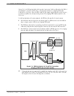
In order to completely install the panel, follow the steps listed.
1.
Mount the DAC I/O panel.
Refer to Figure 11-5.
2.
Install a 50-pin telephony cable between DP1 on the panel and the 50-pin connector on
the back of the VP 300 cabinet corresponding to the first slot containing a DAC card.
For example, DP1 connects to P1, DP2 connects to P2, etc.
The part number for the VP 300 cable is 520-6007-001.
3.
Repeat as necessary for the remaining slots. Install cables only to slots containing
DAC cards.
Do not install a cable to slot A12.
4.
Plug the DC power cable from the power supply into the -48 VDC connector on the
DAC I/O panel.
Switching the system power OFF at the PSU inside the cabinet does not turn OFF the DAC
power supply. The DAC power supply input power cord must be unplugged to turn it OFF.
CAUTION
This unit has more than one power supply cord. To reduce
the risk of electric shock, disconnect both power supply
cords before servicing.
Toshiba VP Systems
Release 6.1
February, 1993
11-10
Installation and Maintenance Manual
Содержание VP 300
Страница 2: ......
Страница 10: ......
Страница 14: ......
Страница 19: ...Quick Reference Guide Hardware Toshiba VP 300 System Specifications Toshiba VP Systems Release 7 1 July 1994 ...
Страница 20: ...Toshiba VP Systems Release 7 1 July 1994 ...
Страница 52: ...Toshiba VP Systems Release 6 1 February 1993 2 14 Installation and Maintenance Manual ...
Страница 56: ...Toshiba VP Systems Release 7 1 July 1994 ...
Страница 146: ......
Страница 312: ...Toshiba VP Systems Release 7 1 July 1994 ...
Страница 314: ......
Страница 444: ......
Страница 496: ......
Страница 542: ......
Страница 598: ...Toshiba VP Systems Release 6 1 February 1993 ...
Страница 600: ...Toshiba VP Systems Release 6 1 February 1993 ...


