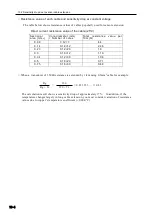
10.5 Compensation method in 1-gauge 4-wire method
10-10
10.5 Compensation method in 1-gauge 4-wire method
○
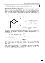
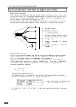
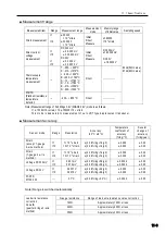
Measurement principle
In the 1-gauge 4-wire system of strain measurement method, no Wheatstone bridge circuit is used
but a simple series circuit is configured with gauge resistance (R) and reference resistance (Rs) to
measure strain. Strain is calculated based on the voltage (V) generated in the gauge resistance
and the voltage (Vs) generated in the reference resistance.
Since the path where the current flows is different from the path where the voltage is measured,
measurement without affection of lead wire resistance and contact resistance (r) is possible.
○ Compensation operation
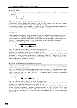
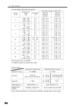
In the 1-gauge 4-wire strain measurement method, when initial unbalance gets larger, the output
voltage “e” which is generated at “V” above is not completely proportional to the strain “ε”.
The TC-32K prepares an operation to compensate the error automatically.
At the time of initial-in, it measures the output voltage “e
0
” which is generated at “V” above in
initial unbalance state, and saves the value in its internal memory. At the time of measurement,
it measures the output voltage “e” under the strain generated condition and performs the
following compensation operation:
ε
m
=
○ Compensation operation setting
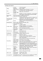
In conjunction with the operation setting, you can select “Perform compensation operation” or
“Not perform compensation operation” in compensation operation.
Comet setting
Compensation operation
Comet NON
Not perform
Comet A
Perform
Comet B
Perform
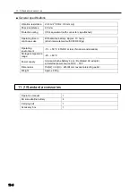
Set “1G4W 120”, “1G4W 240”, or “1G4W 350” in sensor mode setting according to the gauge
resistance.
R : Gauge resistance
Rs: Reference resistance
r
1
~
r
4
: Lead wire resistance
i:
Current passing through gauge
resistance and reference resistance
E : Voltage source
V: Voltage
generated
in
gauge
resistance
V
S
: Voltage generated in reference
resistance
R
r
1
r
2
r
3
r
4
Rs
V
Vs
E
i
When “Not perform” is selected, output
voltage “e” is output as it is.
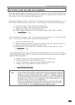
1 + 2 × e
0
e - e
0
Содержание TC-32K
Страница 1: ...O p e r a t i o n M a n u a l TC 32K HANDHELD DATA LOGGER...
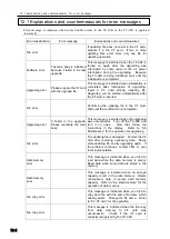
Страница 8: ...Chapter 12 Error Message 12 1 Explanations and countermeasures for error messages 12 2...
Страница 9: ...Chapter 1 Overview 1 1 Overview 1 2 1 2 Features 1 2 1 3 Details about each part 1 3...
Страница 22: ...2 5 Operation outline 2 10 memo...
Страница 23: ...Chapter 3 Sensor Connection 3 1 Sensor connection 3 2...
Страница 65: ...5 10 Measurement auxiliary setting 5 28 memo...
Страница 78: ...6 5 Recording in data memory and CF card 6 13 memo...
Страница 86: ...7 7 Remote measurement 7 8 memo...
Страница 98: ...8 7 Factory setting 8 12 memo...
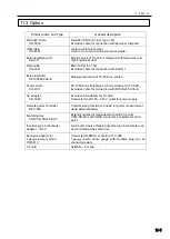
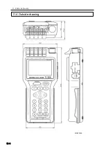
Страница 127: ...11 4 Outside drawing 11 8 11 4 Outside drawing Unit mm...
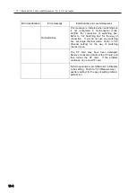
Страница 128: ...Chapter 12 Error Message 12 1 Explanations and countermeasures for error messages 12 2...

