background image

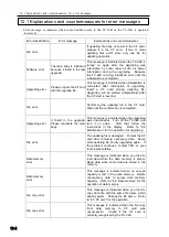
12.1 Explanations and countermeasures for error messages 


12-4 


Error classification 

Error message 

Explanations and countermeasures


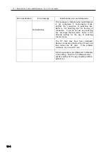
No Switch Box 

This message is indicated when switching box 
is  not  recognized  in  multi-channel  mode.   
Confirm  the  connection  of  switching  box.   
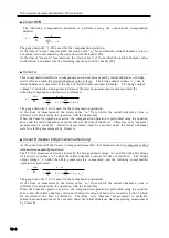
Refer  to 

“9.2  Switching  box”  for  the  way  of 

connection.    If  you  do  not  use  any  switching 
box,  set  single-channel  mode.    Refer  to 

“4.4 

Channel  setting

”  for  the  way  of  switching 

channel mode. 


The  CF  card  may  have  been  damaged.   
Remove necessary data from the CF card, and 
then  format  the  CF  card.    If  the  problem 
continues, use a new CF card.   


Initial-in operation is prohibited (set to Disable) 
in the setting.    Refer to 

“5.10 Measurement 

auxiliary setting

” for the way of setting initial-in 

permission.       


Содержание TC-32K

Страница 1: ...O p e r a t i o n M a n u a l TC 32K HANDHELD DATA LOGGER...

Страница 2: ...he purpose of product improvement If you have any questions or comments regarding contents of this manual such as misdescription inaccuracy and missing items please feel free to contact us The company...

Страница 3: ...flooded dry enough before turning on the power supply If the system does not start normally some trouble might be caused Please contact us Warning The system may malfunction if either the unit or its...

Страница 4: ...tection 2 6 2 4 Screen outline 2 7 Startup screen 2 7 Screen configuration 2 7 2 5 Operation outline 2 8 Operation system 2 8 Key switch 2 9 Key lock 2 9 Chapte 3 Sensor Connection 3 1 Sensor connecti...

Страница 5: ...tting 5 11 5 5 TEDS sensor 5 12 Reading of sensor setting 5 12 Applying the read setting 5 13 5 6 Switching of measurement mode 5 13 5 7 Switching between Measure and Direct 5 14 5 8 Automatic measure...

Страница 6: ...etting 7 3 Communication conditions 7 3 7 3 Data output 7 4 Connection with device 7 4 Data output destination and output procedure 7 4 7 4 Data output format setting 7 5 7 5 External indicator settin...

Страница 7: ...value 9 10 Unavailable function in inclinometer mode 9 11 Chapter 10 Strain Compensation 10 1 Wire connection of strain gauge 10 2 1 gauge 4 wire method 10 2 Quarter bridge 2 wire method 10 2 Quarter...

Страница 8: ...Chapter 12 Error Message 12 1 Explanations and countermeasures for error messages 12 2...

Страница 9: ...Chapter 1 Overview 1 1 Overview 1 2 1 2 Features 1 2 1 3 Details about each part 1 3...

Страница 10: ...ing the interval timer data memory data storage by Compact Flash TM memory card and connection with PC for control and data transfer With the resistance check and insulation resistance check functions...

Страница 11: ...s the functions 6 Cursor key Moves the cursor 7 Ten keys Used for input of values and selection of menu items 8 ENT key Used to fix the setting values and to start of the timer 9 ESC key Used for canc...

Страница 12: ...utton Double push button to remove a CF card 5 CF cover Protection cover for CF card slot 6 NDIS connector cap Protection cap for NDIS connector receptacle 7 Fixing thread Used for fixing of the main...

Страница 13: ...Chapter 2 Preparation 2 1 Instructions for use 2 2 2 2 Power source 2 3 2 3 Instructions for field measurement 2 6 2 4 Screen outline 2 7 2 5 Operation outline 2 8...

Страница 14: ...instrument is equivalent to IP 54 not affected by water splash from any direction Do not let the instrument soak directly in water For waterproof the connector cap and the CF cover must be attached c...

Страница 15: ...ries charge them in advance 1 Rotate the screw anticlockwise with a coin or something and remove the battery hatch Loosened 2 Set four batteries in correct positions 3 Return the battery hatch and rot...

Страница 16: ...or display is ON The CF card is in the slot Ambient temperature is 23 C Operating time using sleep interval Interval time Ambient temperature 23 C Ambient temperature 0 C Single unit of TC 32K CSW 5A...

Страница 17: ...wer ON Press the POWER key for 2 seconds or more The startup screen appears on the main LCD and then the monitor screen is displayed Power OFF Press the POWER key for 2 seconds or more To repeat turni...

Страница 18: ...ay wires down on the ground If it is impossible to lay them down on the ground for example if cables are installed around steel towers use the arrester for sensors mentioned in the next article Arrest...

Страница 19: ...r screen to select To Menu to go to other setting screens and to change settings Soon after you turn on power the startup screen shown in the left appears Then the monitor screen shown below appears M...

Страница 20: ...al measurement Start Stop Various checks Insulation check Resistance check Dispersion check Lead wire resistance check Bridge output check Coefficient setting check Settings for measurement Simple mea...

Страница 21: ...cursor Select monitor channel Increase decrease values 0 9 Input values Select items on Menu ENT START Fixes setting Starts scanning measurement ESC KEY LOCK Cancels setting Moves to higher Menu laye...

Страница 22: ...2 5 Operation outline 2 10 memo...

Страница 23: ...Chapter 3 Sensor Connection 3 1 Sensor connection 3 2...

Страница 24: ...Lever operation Details Extremely thin lead wire Arrow type crimp terminal Take down the lever forward Insert the conductor part of lead wire or the arrowhead of crimp terminal between the terminal b...

Страница 25: ...e connection table Measurement object Wire connection diagram Sensor mode Quarter bridge 2 wire 1G3W 120 1G3W 240 1G3W 350 Quarter bridge 3 wire 1G3W 120 1G3W 240 1G3W 350 1 gauge 4 wire 1G4W 120 1G4W...

Страница 26: ...tage measurement DC voltage 300mV DC voltage 30V DC AUTO up to 30V Pt RTD Platinum resistance temperature detector Pt100 3W Red Green Black White For most of our transducers You cannot use a calibrato...

Страница 27: ...ter 4 Monitor Display and Measurement 4 1 Monitor screen outline 4 2 4 2 Monitor display 4 2 4 3 Initial value processing 4 5 4 4 Channel setting 4 8 4 5 Record of measurement values 4 10 4 6 Sub LCD...

Страница 28: ...ed when multi channel mode is selected The following sections show the examples of the monitor screen and explain items on each screen Value monitor The screen displays measurement values of the selec...

Страница 29: ...g indications are displayed to alert instead of measurement values The indication that appears when a problem occurs and supposed cause are shown below Open data The sensor is not connected or the sen...

Страница 30: ...1 Press F2 key to go to Channel setting from the monitor screen 2 The channel setting screen appears Press F3 key to go to Measurement mode switching screen 3 Press F3 key to go to Monitor type select...

Страница 31: ...irect D is attached to the same In Measure mode value from which the initial value is subtracted is displayed In Direct mode value from which the initial value is not subtracted i e initial value is i...

Страница 32: ...with keys and press ENT key or press 2 of the ten keys to go to Initial in of monitor channel 3 Confirmation message is displayed Move the cursor reversed indication with keys to Yes and press ENT ke...

Страница 33: ...channel that you want to rewrite and press ENT key 4 Input the value directly with ten keys To switch press F1 key To clear the entered value press F3 key After entering the value press ENT key 5 The...

Страница 34: ...o Chapter 9 Increase of the number of measurement points Measurement mode The following four measurement modes are available Select one according to your measurement form Single channel mode Select th...

Страница 35: ...ent mode switching 3 Move the cursor with keys and select a mode 4 Press ENT key The channel setting screen for the selected mode is displayed 1 Press F2 key on the monitor screen to go to Channel set...

Страница 36: ...F card When an external device is connected data are output to the device 1 Confirm that recording on Data memory or CF card is set On For details refer to Chapter 6 Record setting 2 Press ENT START k...

Страница 37: ...measurement function is running no capacity remains in the data memory or the AC adapter is used Lights up when the AC adapter is connected Lights up when the battery voltage goes down Lights up every...

Страница 38: ...3 5 3 Coefficient indication digits and unit 5 6 5 4 Thermocouple RJC setting 5 11 5 5 TEDS sensor 5 12 5 6 Switching of measurement mode 5 13 5 7 Switching between Measure and Direct 5 14 5 8 Automat...

Страница 39: ...of sensors automatic measurement and various checks The configuration of these setting screens is shown below Press F3 key to go to the Menu screen Move the cursor reversed indication with keys and pr...

Страница 40: ...350 Quarter bridge 3 wire 350 2GAGE Half bridge 120 1000 4GAGE Full bridge 120 1000 4G C350 Full bridge constant current 350 4GAGE 0 2V Full bridge 0 2V 120 1000 Bridge excitation voltage DC 2 V 24ms...

Страница 41: ...The list of sensor modes is displayed Move the cursor with keys to the sensor mode you want to set and press ENT key You can change pages of the list with F2 and F3 keys When quarter bridge 3 wire me...

Страница 42: ...nel to another channel are handled as one group 1 Press F3 key on each setting screen to go to Group setting 2 Specify a range group of channels in the From area and To area with ten keys or keys Then...

Страница 43: ...ctor KG is 1 98 and Young s modulus E is 2100000 kgf cm2 steel 2 000 1 98 2100000 10 6 2 121 Set the coefficient as follows Coefficient 2 121 Range Coefficient 0 0001 99999 C kg cm A F m s2 N mm G k k...

Страница 44: ...follows Sensor mode 4GAGE Coefficient 2 000 10 3 Unit mm and Indication digits When measuring a voltage output sensor in direct reading of physical value In case of displacement transducer with capaci...

Страница 45: ...tion digits Move the cursor reversed indication with keys to the indication digits you want to set and press ENT key Setting unit Move the cursor reversed indication with keys to the unit you want to...

Страница 46: ...the cursor to the item you want to set with keys and press ENT key The procedure to set the unit and indication digits are mentioned previously Setting capacity Enter the value directly with ten keys...

Страница 47: ...h keys to an input value and press ENT key 3 The input value is multiplied by the coefficient and the result value is displayed 3 After setting all items press ESC key The screen shown in the left app...

Страница 48: ...y you can go to Group setting 3 Move the cursor to either Internal junction or External junction with keys and press ENT key The TC 32K has a built in temperature sensor inside This temperature sensor...

Страница 49: ...hich you want to read and press F1 key 4 The read setting is temporarily displayed 1 Connect a TEDS compatible sensor to the NDIS connector receptacle When the reading operation completes normally val...

Страница 50: ...t mode refer to the page 8 of Chapter 4 Measurement mode 1 Move the cursor reversed indication with keys on the Program screen and press ENT key or press 5 of ten keys to go to Measurement mode 2 Move...

Страница 51: ...ue is not subtracted D is indicated on the monitor 1 Move the cursor reversed indication with keys on the Menu screen and press ENT key or press 2 of ten keys to go to Measure Direct mode 2 Move the c...

Страница 52: ...s at intervals of 00 hour 04 minute 00 second Twice 03 Measures at intervals of 00 hour 30 minute 00 second Twice In addition Real time start allowing controlling of steps at the execution start time...

Страница 53: ...tting is displayed temporarily as shown in the left Press ENT key again 6 Move the input area with keys and input values with ten keys or keys To enter Endless infinite for the number of repetitions p...

Страница 54: ...Then set End of interval for Step 02 with the similar procedure Now the setting of interval measurement completes Without setting of the step of End of interval measurement is possible 3 The setting...

Страница 55: ...00 second 03 Measure at day 12 hour 00 minute 00 second 04 Go to Step 01 Infinite In this case measurement is started at AM0 00 AM6 00 and PM12 00 Measurement at AM0 00 for Step 01 is executed first...

Страница 56: ...Move the cursor reversed indication to Goto with keys and press ENT key 1 Go to Interval measurement Move the cursor reversed indication to the step to be set with keys and press ENT key 4 Move the c...

Страница 57: ...reduce power consumption However the function does not work in a step with interval of less than 1 minute If all steps are with interval of less than 1 minute the screen shown in the left appears sle...

Страница 58: ...the power with POWER key If you want to cancel the sleep function completely stop the interval measurement Power ON Sleeping Sleeping Sleep Second auto measurement by interval starts 5 seconds before...

Страница 59: ...e or an equivalent which is connected between the input terminal A and B of the TC 32K 1 Move the cursor reversed indication with keys on the Menu screen and press ENT key or press 4 of ten keys to go...

Страница 60: ...al unbalance value of the bridge under current condition in quarter bridge 3 wire method or half bridge common dummy method 1 Move the cursor reversed indication to Dispersion check with keys on the V...

Страница 61: ...een and press ENT key or press 5 of ten keys to go to Setting concerning measurement 2 Move the cursor reversed indication with keys to Simple measure and press ENT key or press 1 of ten keys 2 Move t...

Страница 62: ...RTD 1 2 1 0000 0 1 C DC voltage 300 mV 1 0000 0 001mV DC voltage 30 V 1 0000 0 0001V DC voltage AUTO 3 300mV 1 0000 0 001mV 30V 1 0000 0 0001V 1 When a temperature sensor such as thermocouple is selec...

Страница 63: ...prevent variation or shift when the measurement value is unstable 1 Move the cursor reversed indication with keys on the Setting concerning measurement screen and press ENT key or press 2 of ten keys...

Страница 64: ...ersed indication with keys on the Setting concerning measurement screen and press ENT key or press 4 of ten keys to go to Initial in Permitted 2 To prohibit initial in operation move the cursor to Dis...

Страница 65: ...5 10 Measurement auxiliary setting 5 28 memo...

Страница 66: ...Chapter 6 Record Setting 6 1 Record setting outline 6 2 6 2 Data memory 6 3 6 3 CF card 6 6 6 4 File copy 6 11 6 5 Recording in data memory and CF card 6 12...

Страница 67: ...opy of data from the internal data memory and CF card The configuration of these operations and setting screens are shown below Press F3 key to go to the Menu screen Move the cursor reversed indicatio...

Страница 68: ...and the number of data reaches 80 000 the oldest data is discarded and the latest data is always recorded Channel Measurement time Measurement data Unit 0 80000 40000 Measurement data Record Details o...

Страница 69: ...reversed indication with keys on the Data memory screen and press ENT key or press 2 of ten keys to go to Data memory Data number setting Increase or decrease values with keys or input directly with...

Страница 70: ...cursor to Ok with keys and press ENT key Repeated measurement with ring buffer ON When the data memory capacity is fully occupied and recording of data is in the second cycle or later the indication c...

Страница 71: ...cursor reversed indication with keys on the CF card screen and press ENT key or press 1 of ten keys to go to File dump 2 Move the cursor to the data file to be read with keys and press ENT key 2012 1...

Страница 72: ...d Scroll the screen with keys To see the first part of the data press F2 key To see the last part of the data press F3 key 1 Move the cursor reversed indication with keys on the Data memory screen and...

Страница 73: ...nfirm whether you want to add data appears on the screen Select Ok if you want to add the data When you select Cancel the File name and format screen is restored Cautions for operation of CSV format f...

Страница 74: ...nd press ENT key or press 3 of ten keys to go to File delete 3 Move the cursor to Ok with keys and press ENT key 2 Move the cursor with keys to select a file to be deleted and press ENT key 1 Move the...

Страница 75: ...ENT key 4 The reading operation starts with the indication of progress 1 Move the cursor reversed indication with keys on the CF card screen and press ENT key or press 6 of ten keys to go to Format o...

Страница 76: ...keys or directly input values for the file name 4 After completing the setting press ENT key The copy operation starts with the indication of progress 5 After the copy operation completes the Memory...

Страница 77: ...a memory CF card Recording in data memory To record data in the data memory move the cursor to On with keys and press ENT key 2 Move to the setting you want to select with keys or ten keys Recording i...

Страница 78: ...6 5 Recording in data memory and CF card 6 13 memo...

Страница 79: ...Setting 7 1 Interface setting outline 7 2 7 2 RS 232C setting 7 3 7 3 Data output 7 4 7 4 Data output format setting 7 5 7 5 External indicator setting 7 6 7 6 Cautions for printer setting 7 6 7 7 Rem...

Страница 80: ...tions data output destination and data format and remote measurement from remote sites The configuration of these setting screens is shown below Press F3 key to go to the Menu screen Move the cursor r...

Страница 81: ...conditions 1 Move the cursor reversed indication with keys on the Interface screen and press ENT key or press 1 of ten keys to go to RS 232C 3 Move the cursor reversed indication to the setting item y...

Страница 82: ...elevant connector of the device For more detail refer to the operation manual of each device Data output destination and output procedure Specify the data output destination according to the connected...

Страница 83: ...easurement data In multi channel mode including inclinometer mode the TC 32K executes scanning measurement when you press ENT key and then outputs all measurement data During auto measurement the TC 3...

Страница 84: ...be made as follows 1 For the TC 32K and the printer settings of Baud rate Data bit Parity and Stop bit must be identical to each other 2 For the printer DPU S245 00A E set FLOW CONTROL to RTS CTS 3 F...

Страница 85: ...rols power on off by commands and solar power generation in long term measurement Refer to the operation manual of the remote power controller RPC 05A for more detail Function The TC 32K is controlled...

Страница 86: ...7 7 Remote measurement 7 8 memo...

Страница 87: ...ngs 8 1 Other settings outline 8 2 8 2 Auto power off setting 8 3 8 3 Version information 8 4 8 4 Date and time setting 8 4 8 5 Switching between Japanese English 8 5 8 6 Maintenance 8 5 8 7 Factory s...

Страница 88: ...he maintenance function you can update the software version The configuration of these setting screens is shown below Press F3 key to go to the Menu screen Move the cursor reversed indication with key...

Страница 89: ...o Auto power off 2 Move the cursor with keys to select On or Off 3 When activating the auto power off function On you can set how many minutes the TC 32K waits from non operation state until it is tur...

Страница 90: ...are displayed To go back to the Others screen press ESC key The left screen is an example It may be different from the actual version you are using 1 Move the cursor reversed indication with keys on...

Страница 91: ...age for the screens 1 Move the cursor reversed indication with keys on the Others screen and press ENT key or press 4 of ten keys to go to Language 2 Move the cursor to select Japanese or English with...

Страница 92: ...n the Others screen and press ENT key or press 5 of ten keys to go to Maintenance 2 Move the cursor reversed indication with keys and press ENT key or press 1 of ten keys to go to Backlight LCD 4 Pres...

Страница 93: ...The LCD backlight brightness is fixed and the Maintenance screen is restored 2 Move the cursor with keys to select among 1 Dark 2 Medium and 3 Bright 1 Move the cursor reversed indication with keys o...

Страница 94: ...is fixed and the Maintenance screen is restored 2 Move the cursor reversed indication with keys on the Maintenance screen and press ENT key or press 5 of ten keys to go to Upgrade 4 The upgrading pro...

Страница 95: ...and turn it on again Upgrading error The left screen shows the case where the upgrading process was failed Operate according to the instructions on the screen In some fault cases no information is di...

Страница 96: ...e as the settings just before the execution of factory setting operation 1 Move the cursor reversed indication with keys on the Others screen and press ENT key or press 6 of ten keys to go to Factory...

Страница 97: ...ment 50 Hz Initial in measurement Enable Burnout check setting No Recording related Item Data memory Data number 00000 Ring buffer setting On CF card File name dat000 File format CSV1 Interface relate...

Страница 98: ...8 7 Factory setting 8 12 memo...

Страница 99: ...Chapter 9 Increase of the Number of Measurement Points 9 1 Outline of increase of the number of measurement points 9 2 9 2 Switching box 9 3 9 3 Inclinometer adapter 9 8...

Страница 100: ...mode Many operation procedures are the same with the procedures in the previous sections so the details of those procedures are omitted in this chapter Please also refer to Chapter 4 Monitor Display...

Страница 101: ...surement data and unit of 5 channels Use the CR 655 cable for connection Use of other cables may cause failure Details of data memory Maximum number of measurement times is approximately 29 400 Even i...

Страница 102: ...er of CSW 5B is set by TC 32K Channel indication A channel number consists of 2 digit numbers The upper digit is a box number and the lower digit is a channel of CSW 5B The left screen is the monitor...

Страница 103: ...nnel mode you can select the value monitor or the waveform monitor Monitor type selection Move the cursor to Off Monitor Off Numeric Value monitor or Y T Waveform monitor with keys and press ENT key 2...

Страница 104: ...so the same Program setting Various setting procedures including the sensor mode are similar to the procedures for the single channel mode Concerning the thermocouple RJC it is set for each one box of...

Страница 105: ...ion digits unit and initial value of the channel of the box number Operation procedures of manual measurement and automatic measurement are similar to those for single channel mode Various checks This...

Страница 106: ...consists of measurement time 2 channels 1 channel for 1 axis mode measurement data and unit CR 65 IA 32 Insertion type inclinometer Connect one end of CR 65 to the NDIS connector of the TC 32K and th...

Страница 107: ...mber is set as first axis and a sequential number is set as second axis like 00 01 or 02 03 In 1 axis mode any number from 00 to 19 can be set Monitor display In 2 axis mode two channels are simultane...

Страница 108: ...of 2 axis data for 2 channels To measure and record data manually press ENT START key Automatic measurement for automatic recording is also available The procedures for manual operation and automatic...

Страница 109: ...nclinometer mode The inclinometer mode does not support the following operations and settings Initial value processing Initial in Initial in of monitor channel Rewriting of initial value Menu Measure...

Страница 110: ...nection of strain gauge 10 2 10 2 Sensitivity drop due to sensor cable extension 10 3 10 3 Complete Compensation Method of Strain Comet 10 7 10 4 How to find the lead wire resistance 10 9 10 5 Compens...

Страница 111: ...ance may become too large to be balanced and thermal output caused by the temperature change of the lead wire is mixed with strain reading Also temperature compensation for the strain gauge is not pos...

Страница 112: ...ty drop caused by the lead wire is calculated by the following equation True value Measurement value In case of quarter bridge 3 wire method and half bridge 3 wire method lead wire resistance entered...

Страница 113: ...0 14 0 12 12 2 46 0 23 0 12 20 1 6 0 3 0 18 12 1 19 0 34 0 12 30 1 06 0 5 0 18 20 0 71 0 75 0 18 30 0 48 When a transducer of 350 resistance is extended by 1 km using 0 5mm2 cable for example The cal...

Страница 114: ...if required True value measurement value The sensor mode of the constant current method on TC 32K is 4GAGE C350 All other sensor modes for strain measurement are constant voltage method The sensor mo...

Страница 115: ...p is slightly different especially due to the level of stray capacitance Actual measurement example Sensor cable used k PNCT SB 1 4 0 5SQ 0 5mm2 4 core cabtyre Conductor resistance 70 m m total value...

Страница 116: ...ides three types of operation to compensate errors automatically refer to the page 26 of Chapter 5 Comet setting for selection procedure The TC 32K activates the compensation operations only when the...

Страница 117: ...ensation operation is performed using the equation above and the initial unbalance value recorded at the time of initial in Therefore only measure measurement is available Initial in measurement must...

Страница 118: ...re resistance check V e Bridge output voltage at the time of direct check V Rg Bridge resistance Resistance value of dummy resistance 120 240 and 350 er r Rg 1 e er In the compensation calculation of...

Страница 119: ...pares an operation to compensate the error automatically At the time of initial in it measures the output voltage e0 which is generated at V above in initial unbalance state and saves the value in its...

Страница 120: ...Chapter 11 Specifications 11 1 Specifications 11 2 11 2 Standard Accessories 11 6 11 3 Option 11 7 11 4 Outside Drawing 11 8...

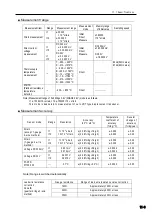
Страница 121: ...dge 0 2V 120 1000 Bridge excitation DC2V 24ms 1 Thermocouple temperature measurement Thermocouple T CC Thermocouple T Digital linearization JIS C1602 1995 Thermocouple K CA Thermocouple K Thermocouple...

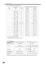
Страница 122: ...n This mode is dedicated to measurement of our LVDT type displacement transducer Measurement accuracy Sensor mode Range Resolution Accuracy 23 C 5 C Temperature coefficient of accuracy rdg C Secular c...

Страница 123: ...0 04 1 2 0 05 0 4 S 10 200 200 1760 0 1 0 1 0 09 0 6 0 07 0 4 0 09 1 2 0 07 0 7 R 10 150 150 1760 0 1 0 1 0 09 0 7 0 07 0 4 0 09 1 2 0 07 0 7 E 210 550 550 1000 0 1 0 1 0 17 0 2 0 09 0 4 0 17 1 4 0 09...

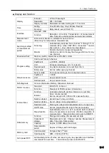
Страница 124: ...to the connected sensor Simple measure Coefficient 1 0000 Unit As per sensor mode Decimal point As per sensor mode Self diagnosis Version information Battery Dispersion Burnout TEDS function Standard...

Страница 125: ...battery Approx 10 hours strain measurement with 350 bridge Operating environment 10 50 C 85 RH or less No dew condensation Storage temperature range 20 60 C Power supply AA size alkaline battery 4 pcs...

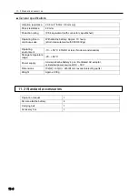
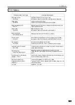
Страница 126: ...straight type 0 5m exclusive for TC 32K Exclusive cable for connection with DPU S245 00A E AC adapter CR 1869 Exclusive AC adapter for TC 32K Connected to AC100 240 V outlet for power supply Remote po...

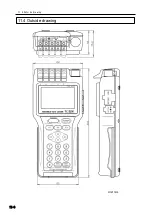
Страница 127: ...11 4 Outside drawing 11 8 11 4 Outside drawing Unit mm...

Страница 128: ...Chapter 12 Error Message 12 1 Explanations and countermeasures for error messages 12 2...

Страница 129: ...he updating file in the CF card Wait until the confirmation is completed Upgrading error It failed in the upgrade Please reactivate the main body This message is indicated when the upgrading was unsuc...

Страница 130: ...the settable range For example settable range for interval timer is 1s 99h 59m 59s This message appears if a value exceeding this range is input ADC error Failure in A D conversion circuit and or com...

Страница 131: ...r to 9 2 Switching box for the way of connection If you do not use any switching box set single channel mode Refer to 4 4 Channel setting for the way of switching channel mode The CF card may have bee...

Страница 132: ...ully examined by our in house inspection division before delivery If it malfunctions due to a manufacturing fault or an accident during shipment please report on the condition to your nearest dealer o...

Страница 133: ...o 140 8560 Japan TEL 03 3763 5611 FAX 03 3763 5713 Handheld Data Logger TC 32K May 2013 8th edition Edited Tokyo Sokki Kenkyujo Co Ltd Issued Tokyo Sokki Kenkyujo Co Ltd URL http www tml jp e E mail a...

Отзывы: