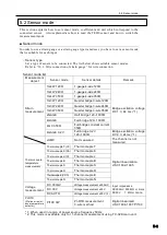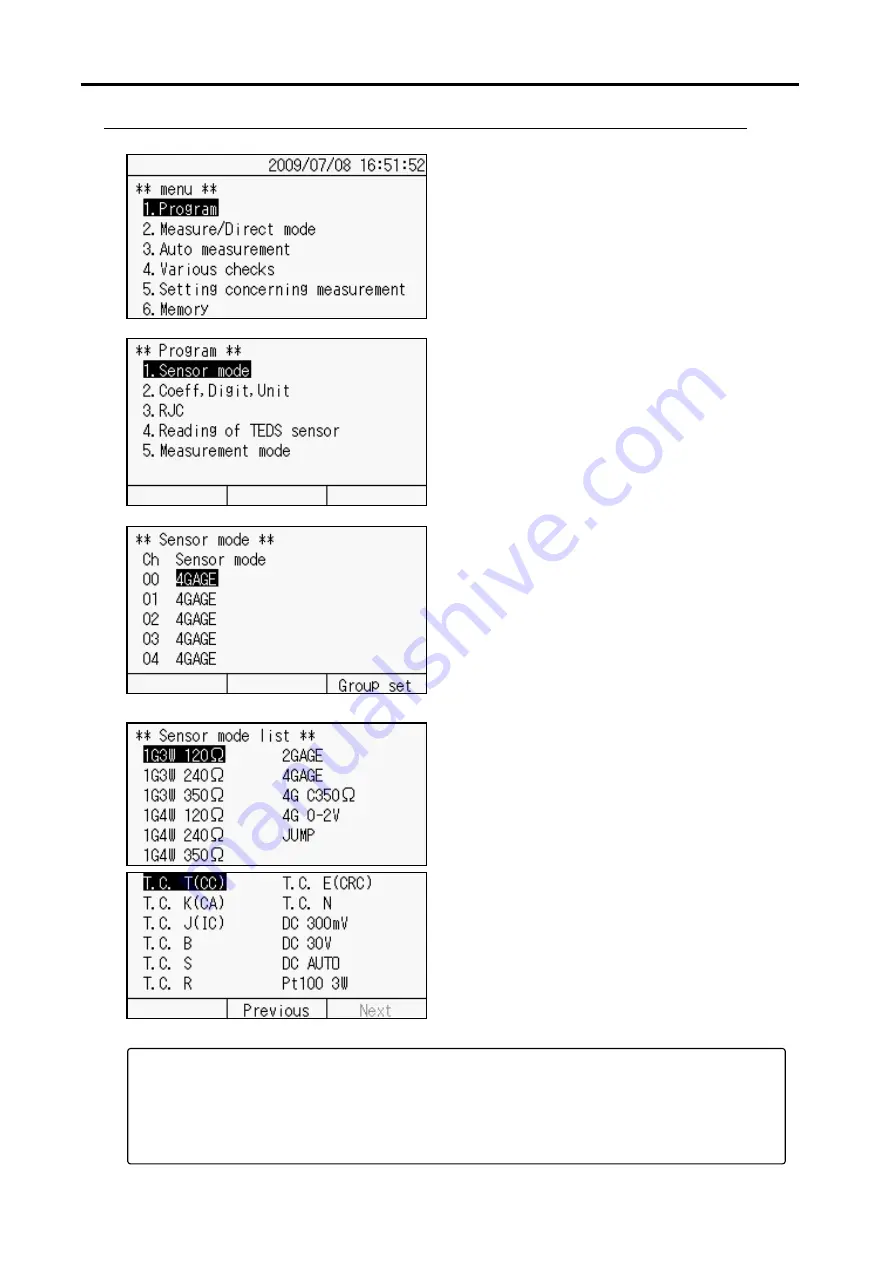
5.2 Sensor mode
5-4
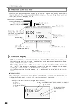
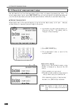
■ Sensor mode setting
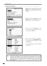
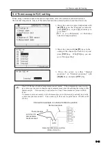
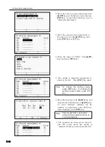
1. Move the cursor (reversed indication) with
[▲][▼]
keys on the Menu screen and press
[ENT]
key, or press
[1]
of ten keys, to go to
“Program”.
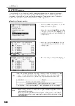
2. Move the cursor (reversed indication) with
[▲][▼]
keys and press
[ENT]
key, or press
[1]
of ten keys, to go to “Sensor mode”.
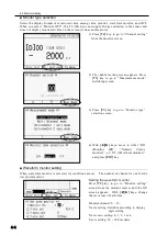
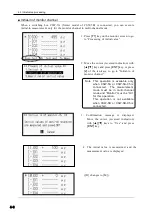
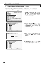
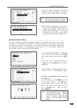
3. Move the cursor with
[▲][▼]
keys to the
sensor mode of the channel that you want
to set, and press
[ENT]
key.
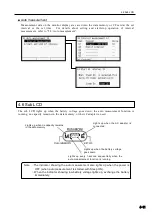
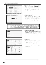
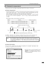
4. The list of sensor modes is displayed.
Move the cursor with
[▲][▼][◄][►]
keys
to the sensor mode you want to set, and
press
[ENT]
key.
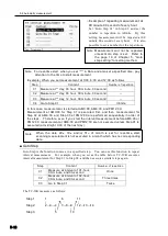
You can change pages of the list with [
F 2]
and [
F 3]
keys.
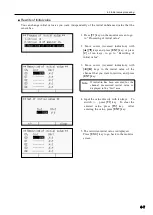
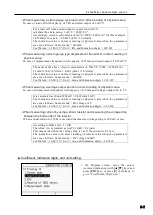
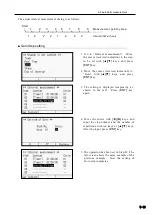
When quarter bridge 3-wire method is selected for sensor mode, and also Comet A or
Comet B is used together, correction calculation is applied automatically to initial
unbalance value and both-ends voltage of lead wire resistance. As a result,
these channels are set to Measure and [m] is indicated on the monitor screen.
For details of Comet, please refer to
“10.3: Complete Compensation Method of
Strain (Comet)
”.
Note
Содержание TC-32K
Страница 1: ...O p e r a t i o n M a n u a l TC 32K HANDHELD DATA LOGGER...
Страница 8: ...Chapter 12 Error Message 12 1 Explanations and countermeasures for error messages 12 2...
Страница 9: ...Chapter 1 Overview 1 1 Overview 1 2 1 2 Features 1 2 1 3 Details about each part 1 3...
Страница 22: ...2 5 Operation outline 2 10 memo...
Страница 23: ...Chapter 3 Sensor Connection 3 1 Sensor connection 3 2...
Страница 65: ...5 10 Measurement auxiliary setting 5 28 memo...
Страница 78: ...6 5 Recording in data memory and CF card 6 13 memo...
Страница 86: ...7 7 Remote measurement 7 8 memo...
Страница 98: ...8 7 Factory setting 8 12 memo...
Страница 127: ...11 4 Outside drawing 11 8 11 4 Outside drawing Unit mm...
Страница 128: ...Chapter 12 Error Message 12 1 Explanations and countermeasures for error messages 12 2...

