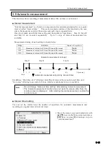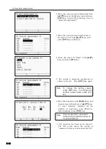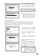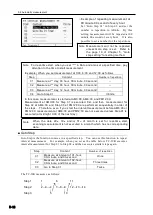
5.2 Sensor mode
5-3
5.2 Sensor mode
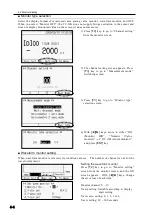
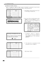
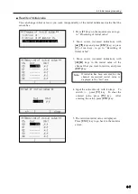
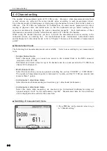
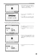
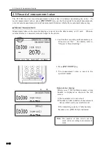
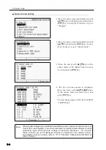
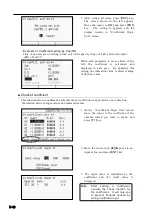
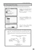
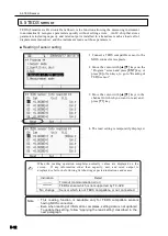
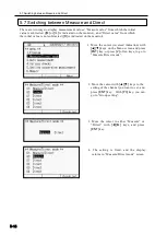
This section explains how to set sensor mode, coefficient and unit which correspond to the
connected sensor. Also explained are how to read the TEDS sensor and how to switch the
measurement mode.
■ Sensor mode
In order to use a strain gauge or a strain gauge type transducer, you have to set a sensor mode
that is suitable for each input.
○
Sensor type
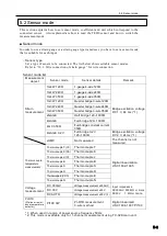
Set a type of sensor to be connected. The list below shows settable sensor modes.
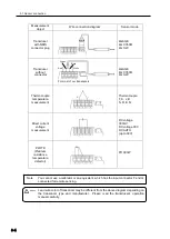
Refer to “10.1: Wire connection of strain gauge” for wire connection.
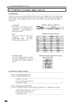
Sensor mode list
Measurement
object
Sensor mode
Sensor details
Remark
Strain
measurement
1G4W 120Ω
1-gauge 4-wire
120Ω
Bridge excitation voltage
DC 1 V, 44 ms (*1)
1G4W 240Ω
1-gauge 4-wire 240
Ω
1G4W 350Ω
1-gauge 4-wire 350
Ω
1G3W 120Ω
Quarter bridge 3-wire
120Ω
1G3W 240Ω
Quarter bridge 3-wire 2
40Ω
1G3W 350Ω
Quarter bridge 3-wire 35
0Ω
2GAGE
Half bridge 120~
1000Ω
4GAGE
Full bridge 120~
1000Ω
4G C350Ω
Full bridge constant current
350
Ω
4GAGE 0-2V
Full bridge 0-2V
120~
1000Ω
Bridge excitation voltage
DC 2 V, 24ms (*1)
JUMP
Not measured
The channel is not
measured.
Thermocouple
temperature
measurement
Thermocouple T(CC)
Thermocouple T
Digital linearization
JIS C1602-1995
Thermocouple K(CA)
Thermocouple K
Thermocouple J(IC)
Thermocouple J
Thermocouple B
Thermocouple B
Thermocouple S
Thermocouple S
Thermocouple R
Thermocouple R
Thermocouple E(CRC)
Thermocouple E
Thermocouple N
Thermocouple N
Voltage
measurement
DC 300mV
Voltage measurement ±300mV
Input impedance
DC300mV 500
MΩ or more
DC30V 1
MΩ or
more
DC 30V
Voltage measurement ±30 V
DC AUTO
Voltage measurement ±30V
(*2)
Pt-RTD
(Platinum resist-
ance temperature
detector)
Pt100 3W
Pt-RTD measurement
3-wire method
Digital linearized
JIS C1604-1997 Pt100
*1: When used in region of power source frequency 50Hz
*2: This mode is available only for 1-channel measurement using TC-32K main unit.
Содержание TC-32K
Страница 1: ...O p e r a t i o n M a n u a l TC 32K HANDHELD DATA LOGGER...
Страница 8: ...Chapter 12 Error Message 12 1 Explanations and countermeasures for error messages 12 2...
Страница 9: ...Chapter 1 Overview 1 1 Overview 1 2 1 2 Features 1 2 1 3 Details about each part 1 3...
Страница 22: ...2 5 Operation outline 2 10 memo...
Страница 23: ...Chapter 3 Sensor Connection 3 1 Sensor connection 3 2...
Страница 65: ...5 10 Measurement auxiliary setting 5 28 memo...
Страница 78: ...6 5 Recording in data memory and CF card 6 13 memo...
Страница 86: ...7 7 Remote measurement 7 8 memo...
Страница 98: ...8 7 Factory setting 8 12 memo...
Страница 127: ...11 4 Outside drawing 11 8 11 4 Outside drawing Unit mm...
Страница 128: ...Chapter 12 Error Message 12 1 Explanations and countermeasures for error messages 12 2...

