10.2 Sensitivity drop due to sensor cable extension
10-3
10.2 Sensitivity drop due to sensor cable extension
■
Measurement by constant voltage method
The constant voltage method, where the bridge excitation voltage is kept constant at instrument’s
terminal, is generally used for measuring strain. When a sensor cable between the instrument
and the strain gauge bridge is extended, this method causes sensitivity drop because the voltage
decreases by the cable resistance and the excitation voltage applied to the bridge is also decreased.
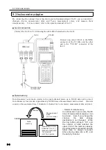
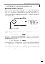
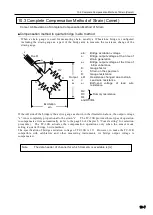
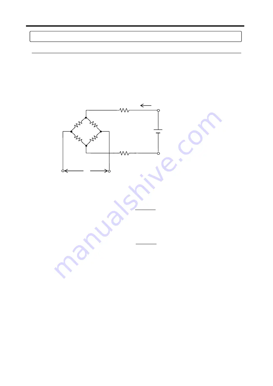
The illustration below shows an equivalent circuit in a case where full bridge method is used for
extending a sensor cable.
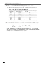
In case of quarter bridge 2-wire method, half bridge common dummy method, and full bridge
method, a true value excluding the sensitivity drop caused by the lead wire is calculated by the
following equation:
True value = Measurement value ×
In case of quarter bridge 3-wire method and half bridge (3-wire) method, lead wire resistance
entered in one bridge arm is the resistance of one way of the lead wire, and a true value is
calculated by the following formula:
True value = Measurement value ×
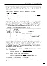
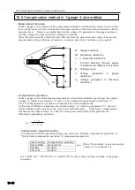
In case of quarter bridge 3-wire method, when Comet B is set for the compensation method,
TC-32K measures the lead wire resistance and acquires correct measurement values after proper
compensation.
When Comet A or Comet B is set, TC-32K activates compensation including initial values.
Therefore, the compensation calculation equation above are not appropriate. For more detail,
refer to “10.3 Complete Compensation Method of Strain”.
Rg + r
Rg
r
r
I
C
B
D
E
A
Rg: Bridge input resistance
r: Cable resistance
E: Bridge excitation voltage
I: Bridge excitation current
e: Bridge output voltage
*A, B, C, and D: Instrument (or switching box)
terminals
Rg
e
Rg + 2r
Rg
Содержание TC-32K
Страница 1: ...O p e r a t i o n M a n u a l TC 32K HANDHELD DATA LOGGER...
Страница 8: ...Chapter 12 Error Message 12 1 Explanations and countermeasures for error messages 12 2...
Страница 9: ...Chapter 1 Overview 1 1 Overview 1 2 1 2 Features 1 2 1 3 Details about each part 1 3...
Страница 22: ...2 5 Operation outline 2 10 memo...
Страница 23: ...Chapter 3 Sensor Connection 3 1 Sensor connection 3 2...
Страница 65: ...5 10 Measurement auxiliary setting 5 28 memo...
Страница 78: ...6 5 Recording in data memory and CF card 6 13 memo...
Страница 86: ...7 7 Remote measurement 7 8 memo...
Страница 98: ...8 7 Factory setting 8 12 memo...
Страница 127: ...11 4 Outside drawing 11 8 11 4 Outside drawing Unit mm...
Страница 128: ...Chapter 12 Error Message 12 1 Explanations and countermeasures for error messages 12 2...


