


Pathfinder DVL Guide
April
2018
EAR-Controlled Technology Subject to Restrictions Contained on the Cover Page.
Page 37
Beam Clearance
Acoustic obstacles such as cables, hull, other instruments, etc. are numerous on undersea vehicles. Special
care should be observed in clearing the DVL beams of any acoustic obstacles. A 90 degree cone around the
face of the transducer should be observed to account for each beam acoustic spread. This Beam clearance
should be observed when Bottom Tracking, Water Tracking and Water Profiling. Any acoustic obstacle in
the Main Beam and acoustic spread will interfere with the DVL measurement or worse prevent the meas-
urement altogether. If the DVL is used near a quay wall for instance, then a quick rule of thumb is that for
every meter of vertical separation between the DVL face and the seabed the same separation is necessary
between the DVL and the Quay wall. DVL transducers also have side lobes, which could collect energy
backscattered by acoustic obstacles in the beam clearance cone as shown in the
. This is mostly critical when performing Water Tracking or Water Profiling.
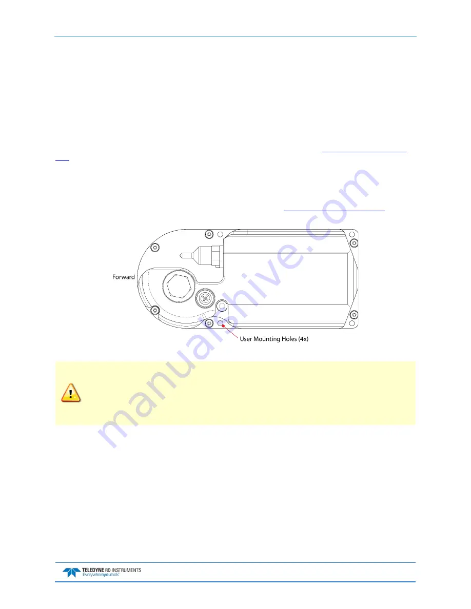
Mounting the Instrument
There are many options for mounting the Pathfinder systems and they depend on the application. Use the
four mounting holes on the transducer (ROV version only). See the
for di-
mensions and weights.
Figure 21.
End-Cap view of the transducer showing mounting holes
Your Pathfinder DVL transducer housing is made of aluminum that is protected by sacrificial
anodes and a hard anodize coat and paint.
Do not connect other metal to the DVL.
Other
metals may cause corrosion damage.
Use M6 isolating bushings and washers when mounting the DVL to a metal structure. Keep
this in mind when fabricating a fixture, which materials to use, or deciding how to place it on
the vehicle.
Pitch & Roll
Pitch and Roll should be limited to avoid a beam pointing vertically toward the bottom. The Pathfinder
DVL beams are slanted 30 degrees from the DVL vertical axes. This beam angle was selected as the best
trade-off between velocity accuracy, resolution and acoustic energy throughout the water column
(which is greater for greater smaller angles).
Moreover, a DVL can only measure velocity relative to itself by measuring the Doppler shift along each
beam. If a DVL beam were to be pointing vertically towards the sea bottom then it would be unable to
measure the Doppler effect of a DVL motion parallel to the sea bottom. Therefore, the DVL should never
be tilted 30 degrees so that a beam would be pointing vertically at the medium of reference, i.e. sea bot-
tom or ice.