


April
2018
Pathfinder DVL Guide
Page 128
EAR-Controlled Technology Subject to Restrictions Contained on the Cover Page.
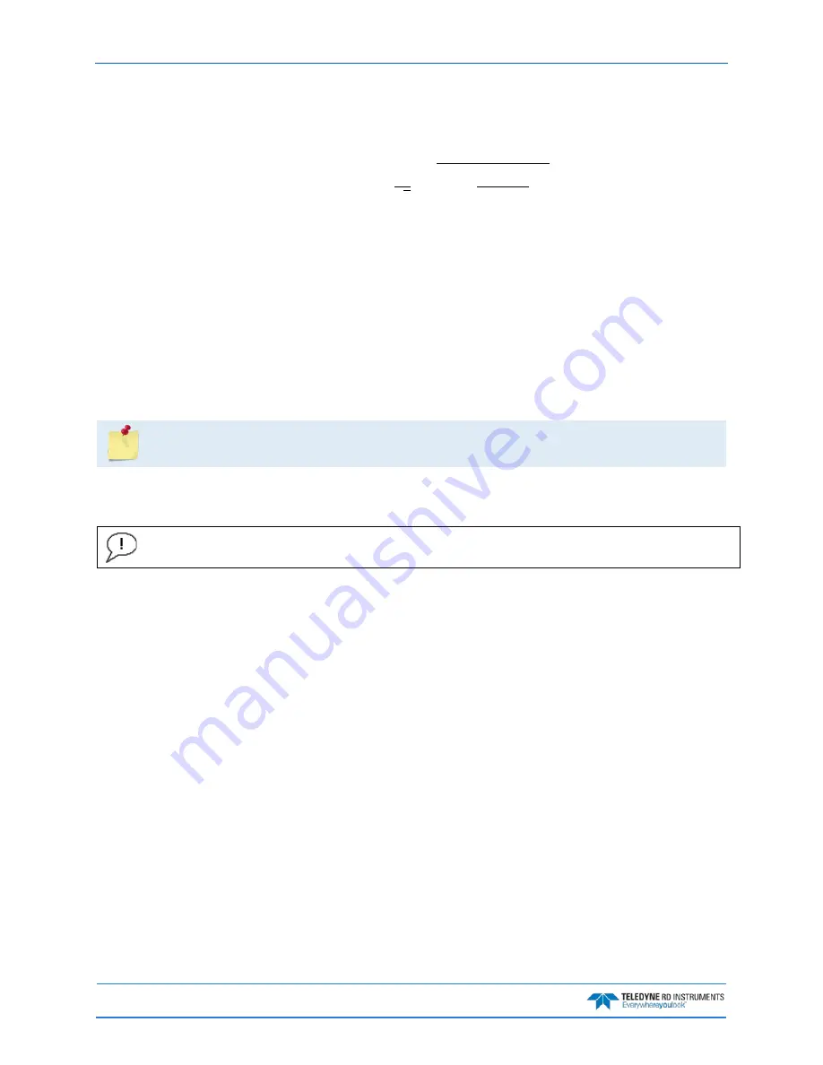
Vertical Range correction for Phased Arrays:
If the user setup for using manual SoS, i.e. using EC instead of sending in the actual SoS or instead of hav-
ing the DVL calculate the SoS, then the equation for correcting altitude is:
𝑅𝑅
𝐶𝐶𝑜𝑜𝑢𝑢𝑢𝑢𝑢𝑢𝑎𝑎𝑎𝑎𝑢𝑢𝑑𝑑
=
𝑅𝑅
𝑅𝑅𝑎𝑎𝑅𝑅
∗
2
√
3
∗
��
1
−
�
𝐶𝐶
𝑎𝑎𝑎𝑎𝑎𝑎𝑎𝑎𝑎𝑎𝑎𝑎
2
∗
𝐶𝐶
𝑎𝑎𝑢𝑢𝑢𝑢𝑢𝑢
�
2
�
Where
C
user
is the fixed speed of sound that was set by the user
C
actual
is the speed of sound from a SoS sensor or computed from measured temp and salinity
R
Raw
is the vertical range to bottom obtained by the averaging the 4 vertical ranges to the bottom from
DVL (‘vertical’ here means DVL vertical axis, i.e. not tilt corrected)
#EI - Roll Misalignment Angle
Purpose
Corrects for a physical roll-like misalignment between the x-axis of the instrument and
the ship’s starboard axis.
Format
#EI±nnnnn
The #EI command must be sent with the # sign.
Range
±nnnnn = -17999 to 18000 1/100ths of a degree
Default
#EI0
Set as needed.
Description
#EI is a rotation about the ship’s forward axis. It is defined as the roll of the ship when
the instrument is level.
For systems that have a roll source referenced to ship coordinates (typical for vehicles),
use #EI to set the amount of rotation that the instrument’s x-axis is physically offset from
the ship’s starboard axis. For such systems, the #EI command can also be used to align an
upward pointing unit (e.g., mounted on a submarine) to the ship’s axis by setting it to
18000.
For systems that have attitude referenced to internal coordinates, #EI is typically set to
zero since the velocity data is referenced to either beam, instrument or geographic coordi-
nates instead of ship coordinates.
For an upward pointing unit with instrument referenced attitude, use EU to align the in-
strument attitude data with the ship coordinates for use in velocity transformation.