


Edit Menu
3Ć42
DG2030 User Manual
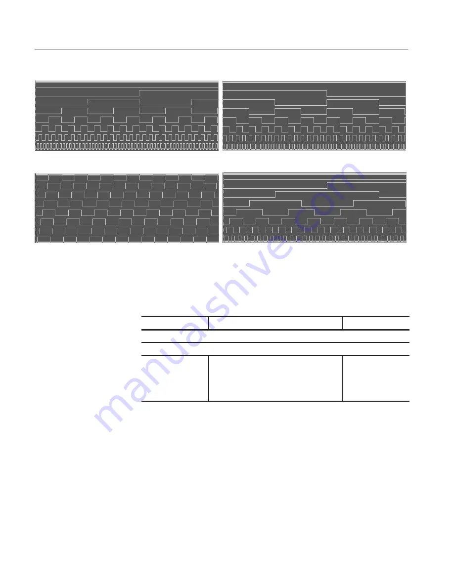
Binary Up Counter
Binary Down Counter
Johnson Counter
Graycode Counter
Figure 3Ć36: Standard pattern data
Operation.
Creating the standard pattern data
Bottom button
Popup menu
Side button
Set the editing range in the point direction.
Set the editing range in the group/bit direction.
Execute Action
Select from the following items.
Binary up counter
Binary down counter
Johnson counter
Graycode counter
OK
Artisan Technology Group - Quality Instrumentation ... Guaranteed | (888) 88-SOURCE | www.artisantg.com


