


Malfunctions and remedy
Super-Vitesse CFS 3101, 3501 / Super-Vitesse CFS 3101 DO, 3501 DO 10.13
207
13.2
Electrics
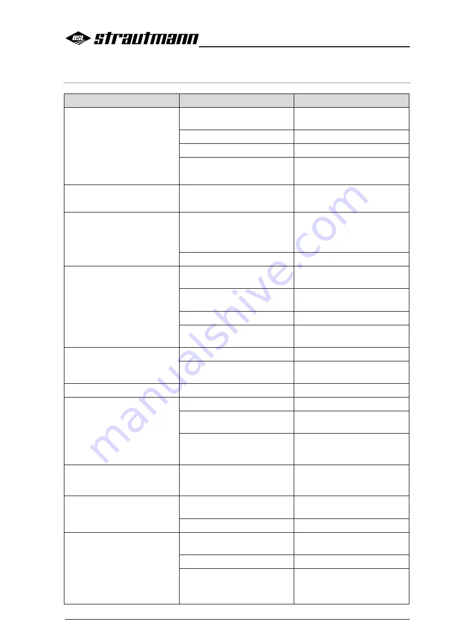
Malfunction
Cause
Remedy
No function working
No power at the control set
Provide a voltage of 12 V at the
tractor
Defective fuse
Replace fuse
Loose contact in socket
Remedy loose contact
Operating element On/Off not
switched
Set operating element to On
Functions work irregularly
Cable cross section of feed line
too small
Select larger cable cross section
Fuse at tractor often defective
Fuse protection too weak
Install a fuse of min. 25 A, check
cable cross sections (rated
cable cross section = min.
4 mm
2
)
Damaged cable
Replace cable
Feed function cannot be
controlled
No power, 12 V at the control
set
Provide a voltage of 12 V at the
tractor
Cable cross section of feed line
too small
Select larger cable cross section
Defective control set
Have control set checked
Defective solenoid of a hydraulic
valve
Replace solenoid
Feed function can only
temporarily be controlled
Loose contact at solenoid
Remedy loose contact
Cable cross section of feed line
too small
Select larger cable cross section
Feed function does not work
Defective solenoid of feed
Replace solenoid
2 or more functions work
simultaneously
Damaged cable
Replace cable
Several simultaneously
energised solenoids
Check cable
Emergeny manual operation
function actuated
Check whether knurled screws
of control block are unscrewed,
unscrew if necessary
Function does not work although
a voltage of 12 V is available at
the solenoid
Defective solenoid
Replace solenoid
Display of control set does not
work
No 12 V voltage
Provide a voltage of 12 V at the
control set
Defective fuse at the tractor
Replace fuse
The display of a function does
not show a status message on
the control set
Defective wiring (short-circuit)
Check wires, replace them if
necessary
Sensor not properly set
Adjust sensor
Defective sensor
Replace sensor