Procedure
1.
Switch on the switch in the analyzer.
2.
Switch on the F1 (FB1) in the sample conditioning and distribution unit.
3.
Switch on the fuse of heated sample gas line 1 (FC1).
✓
Switch on the heated sample gas line and heating controller.
4.
Switch on the SFU 1 (FC2) fuse.
✓
SFU and heating controller switch on.
5.
Switch on the fuse of the cooler, condensate pump, sample gas pump, power
supply unit (FC3).
✓
Cooler turns on.
✓
Instrument air is fed to the gas sampling unit.
✓
The gas sampling unit is purged during the heating phase (standby).
✓
Condensate pump starts (direction of rotation left).
6.
Switch on the analyzer fuse (FC4).
✓
Analyzer and display switch on.
7.
Switch on the fuse of heated sample gas line 2 (FC5).
✓
Heated sample gas line 2 switches on.
8.
Switch on the SFU 2 (FC6) fuse.
✓
SFU 2 switches on.
✓
After the heating phase (about 2 hours), the analyzer goes into measuring mode.
7.2
Connecting with SOPAS ET
Procedure
1.
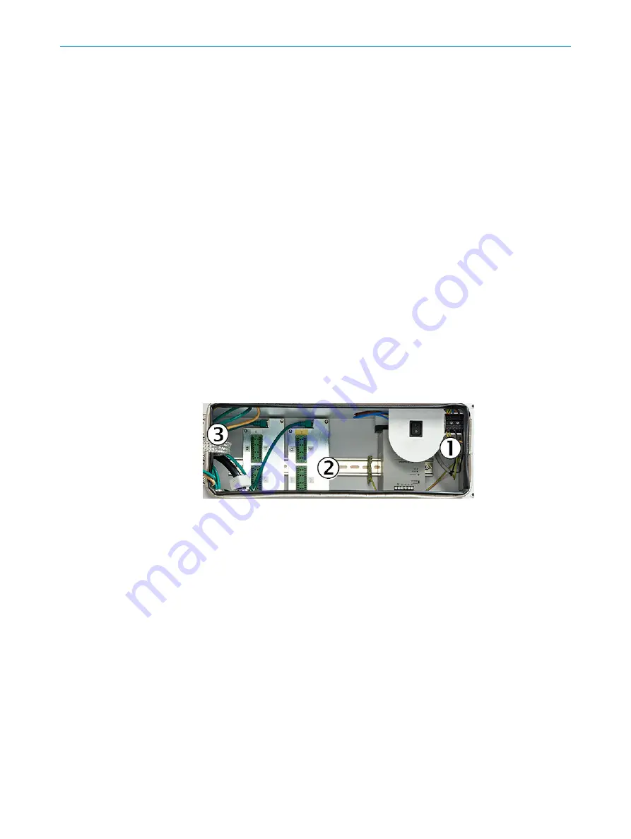
Connect the network cable to distribution board
3
.
1
Power voltage connection at terminal strip
2
Signal connections (I/O)
3
Distributor board with Ethernet for MPR (option), Modbus, service interface (LAN)
✓
Analyzer and computer are connected.
2.
Open the SOPAS ET engineering tool
✓
SOPAS automatically searches for available devices in the network.
3.
If only the BCU is displayed, the IP address of the analyzer is in a different number
range than the laptop. This needs to be adjusted.
4.
After changing the IP address, delete the BCU from the Project window with Del.
5.
Perform the search with “Search device”.
✓
All modules installed in the device are displayed.
6.
Select the modules and drag them into the Project window on the left.
✓
The connection with the device is established.
Related topics
•
Changing the IP address on the BCU:
see "Changing the IP address on the BCU",
COMMISSIONING
7
8021339/1CHC/V1-1/2021-07 | SICK
O P E R A T I N G I N S T R U C T I O N S | MARSIC280
49
Subject to change without notice


