PN-L803C/80TC3 INSTALLATION, ADJUSTMENT, SETTING, OPERATION 2 - 35
- When the function button is pressed, the battery indicator
illuminates. If the battery indicator does not illuminate, check if
the battery is depleted.
- Use function buttons near the front of the screen. If too far away,
operation will not be possible.
- Press function buttons slowly and firmly. If pressed too quickly,
the action may not be recognized.
- The line may break if the touch pen battery is low or there is
other wireless equipment in operation nearby.
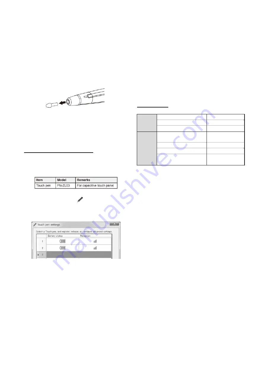
- If the pen tip becomes worn or damaged, replace it.
* When inserting the pen tip, insert firmly all the way in.
■
Touch pen settings
Touch pen settings are configured using the Touch Pen Utility.
For details on the settings and how to use the utility, see the Touch
Pen Utility Operation Manual.
4- 6. Adding touch pens (pairing)
- Up to 4 touch pens can be used simultaneously. (Up to 10 touch
pens can be registered.)
- To use an optional touch pen with the monitor, the touch pen
must be registered in the touch pen adapter. (pairing)
Perform touch pen pairing for one pen at a time.
1. Click the touch pen utility icon (
) on the taskbar.
2. Click [Touch pen settings].
3. Select a line in the touch pen settings screen that does not have
a pen registered, and touch [Registration].
4. Simultaneously hold down function button 1 and function button
3 of the touch pen being paired for at least 5 seconds.
5. When the battery indicator blinks twice or more, release
function button 1 and function button 3. A message appears
after completion of pairing.
6. Touch [OK].
(MEMO)
- When multiple touch pens are used, touch positions and touch
pen information (color, thickness, etc.) may become
interchanged, and lines may break.
- When touched simultaneously
- When touch pens are moved near each other
- When batteries are low
- When other wireless equipment is operating nearby
- Do not press the pen tip on other than the screen. This may
cause malfunctioning.
- One touch pen cannot be registered in multiple touch pen
adapters.
4- 7. LED State
Normal
state
Standby state
*1
LED is OFF
Function switches ON
LED is ON
Pen switches ON
LED is OFF
Special
state
Pearing/Selecting with
thedriver menu
LED flashes (1)
*2
Error occurs
LED flashes (2)
*3
Firmware update is permitted
LED is ON
Data is being received or data
is being revised
LED flashes (3) *
4
*1
:
Standby state
:
Moves to low power consumption
modewithout pen operation in 60 seconds
*2
:
LED flashes (1)
:
1second ON ->
1
second OFF ->(Repeat)
*3
:
LED flashes (2)
:
0.5 secoinds ON
→
0.5 secoinds OFF ->0.5
secoinds ON -> 0.5 secoinds OFF -> 0.5
secoinds ON -> 3.5 secoinds OFF ->
(Repeat)
*4
:
LED flashes (3)
:
0.5 secoinds ON -> 0.5 secoinds OFF ->
(Repeat)
Содержание PN-80TC3
Страница 150: ...PN L803C 80TC3 DISASSEMBLY AND ASSEMBLY 6 6 3 Remove the four screws M3x6 SW W Then remove LED Power Supply PWB ...
Страница 183: ...PN L803C 80TC3 TROUBLESHOOTING 7 10 FUSE POSITION MAIN PWB F2200 F2300 F2102 F2302 F2101 ...
Страница 184: ...PN L803C 80TC3 TROUBLESHOOTING 7 11 5V POWER SUPPLY PWB F2100 F2100 ...
Страница 191: ...PN L803C 80TC3 HARDWARE DESCRIPTIONS 8 7 3 BLOCK DIAGRAM Block diagram ...
Страница 202: ...PN L803C 80TC3 HARDWARE DESCRIPTIONS 8 18 5 PARTS LAYOUT Main PWB TOP ...
Страница 203: ...PN L803C 80TC3 HARDWARE DESCRIPTIONS 8 19 BOTTOM ...
Страница 204: ...PN L803C 80TC3 HARDWARE DESCRIPTIONS 8 20 LED Power Supply PWB TOP ...
Страница 205: ...PN L803C 80TC3 HARDWARE DESCRIPTIONS 8 21 BOTTOM ...
Страница 206: ...PN L803C 80TC3 HARDWARE DESCRIPTIONS 8 22 Key PWB TOP BOTTOM ...
Страница 208: ...PN L803C 80TC3 HARDWARE DESCRIPTIONS 8 24 5V Power Supply PWB connector Upper pin 5V Output Lower pin GND ...


