PN-L803C/80TC3 SERVICE MENU/VARIOUS SETTING TOOL OPERATING PROCEDURES 4- 53
24. CHANGE TOUCH PEN COMMUNICATION CHANNEL(EXTERNAL PC)
24-1. INSTALL TOUCH PENN UTILITY
1) Prepare the PC and install the Touch Pen Utility.
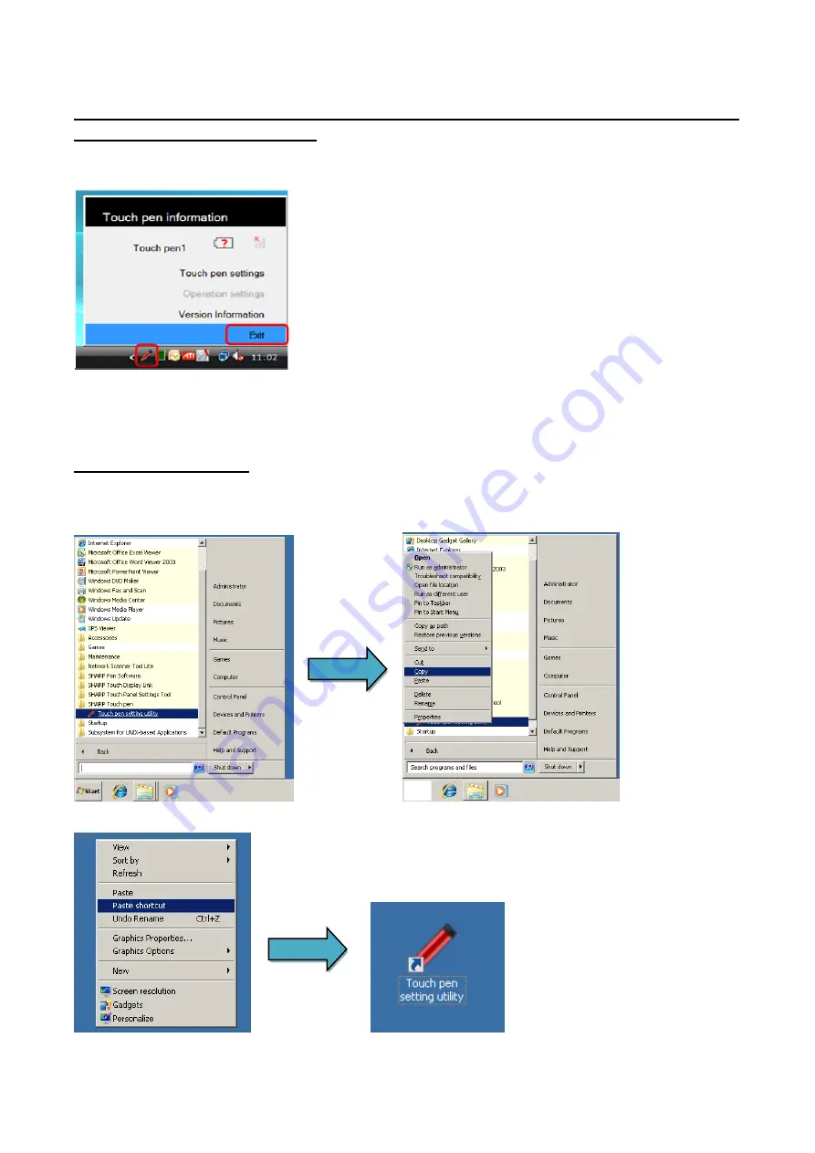
2) After install the Touch Pen Utility, the Touch Pen Utility is started up in the user mode. Then, exit the Touch Pen Utility.
Click the icon of the Touch Pen Utility on the task bar and select the [Exit].
3) Not to start up the Touch Pen Utility in the user mode, delete the Touch pen setting utility from the all programs of the start up menu.
24-2. CREATE SHORT CUT
To start up the Touch Pen Utility in the Service Mode, create the short-cut icon for the start up.
1) From the start up menu, click the SHARP Touch pen in the all programs. Then, right-click the Touch pen setting utility and select the
[Copy].
2) Right-click on the desktop and select the [Paste]. Then, the short-cut icon is created on the desktop.
Содержание PN-80TC3
Страница 150: ...PN L803C 80TC3 DISASSEMBLY AND ASSEMBLY 6 6 3 Remove the four screws M3x6 SW W Then remove LED Power Supply PWB ...
Страница 183: ...PN L803C 80TC3 TROUBLESHOOTING 7 10 FUSE POSITION MAIN PWB F2200 F2300 F2102 F2302 F2101 ...
Страница 184: ...PN L803C 80TC3 TROUBLESHOOTING 7 11 5V POWER SUPPLY PWB F2100 F2100 ...
Страница 191: ...PN L803C 80TC3 HARDWARE DESCRIPTIONS 8 7 3 BLOCK DIAGRAM Block diagram ...
Страница 202: ...PN L803C 80TC3 HARDWARE DESCRIPTIONS 8 18 5 PARTS LAYOUT Main PWB TOP ...
Страница 203: ...PN L803C 80TC3 HARDWARE DESCRIPTIONS 8 19 BOTTOM ...
Страница 204: ...PN L803C 80TC3 HARDWARE DESCRIPTIONS 8 20 LED Power Supply PWB TOP ...
Страница 205: ...PN L803C 80TC3 HARDWARE DESCRIPTIONS 8 21 BOTTOM ...
Страница 206: ...PN L803C 80TC3 HARDWARE DESCRIPTIONS 8 22 Key PWB TOP BOTTOM ...
Страница 208: ...PN L803C 80TC3 HARDWARE DESCRIPTIONS 8 24 5V Power Supply PWB connector Upper pin 5V Output Lower pin GND ...


