background image

PN-L803C/80TC3 TROUBLESHOOTING 7 - 7 

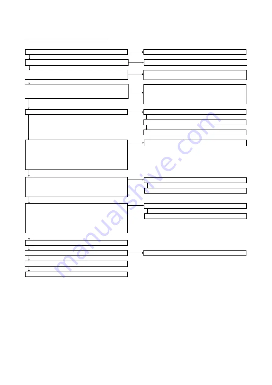
11. TOUCH PEN ABNORMALITY 

 TOUCH PEN IS NOT FUNCTIONAL / RECOGNIZED 

No

Is the touch pen adaptor inserted?

Insert the touch pen adapter

Yes

No

Does the green LED light whe the B1, B2 or B3 button is
pressed?

Change the battery of the touch pen.

Yes

No

Are the touch pen driver and the touch pen utility installed?

Install  the touch pen driver and the touch pen utility.

Is the touch pen utility icon resident on the taskbar?

When the touch pen utility is not started up, stars up the
touch pen utility.

Yes

No

Is the icon of touch pen utility icon on the taskbar red?

Whe the icon is gray, the touch pen adaptor is abnormal.

Yes

Replace the touch pen adaptor.

Register the pen. (pairing) *1

No

Are the name of the touch pen "Touch pen*" and the icons of
the battery status and the reception on the "Touch pen
information" window displayed when the touch pen utility icon
on the taskbar is clicked?

Register the pen. (pairing) *1

(There is no problem when "?" or "X" mark is displayed
beside the battery status and the reception icons. )

Yes

No

Is the

mark is displayed beside the "Touch pen*" on

the"Touch pen information" window when the touch pen
utility icon on the taskbar is clicked and press the tip of the
touch pen?

Change the communication channel of the touch pen.

Yes

Register the pen. (pairing) *1

Does the reception icon on the"Touch pen information"
window show the weak state when the touch pen utility icon
on the taskbar is clicked?

The state is : "X" mark is displayed beside the reception

icon or the only the one antenna is displayed as the reception
state.)

No

Touch pen abnormality

Replace the touch pen.

Register the pen. (pairing) *1

*1 When the registration of the pen (pairing) is not performed, replace the touch pen.

Change the communication channel of the touch pen.

Register the pen. (pairing) *1

Yes

Yes

Is the “Capacitive” written on the Touch pen?

Use the Touch pen with the “Capacitive” mark.

No

Is this symptom removed by replacing the pent tip (felt) ?

Replace the pen tip (Discard the used pen tip.).

Yes

No

No

No


Содержание PN-80TC3

Страница 1: ...SHARP CORPORATION Model Name Countries PN L803C North America PN 80TC3 Other countries CHAPTER 1 OUTLINE OF THE PRODUCT 1 1 CHAPTER 2 INSTALLATION ADJUSTMENT SETTING OPERATION 2 1 CHAPTER 3 INPORTANT INFORMATION FOR SERVICING THE DISPLAY 3 1 CHAPTER 4 SERVICE MENU VARIOUS SETTING TOOL OPERATING PROCEDURES 4 1 CHAPTER 5 FIRMWARE UPDATE PROCEDURES 5 1 CHAPTER 6 DISASSEMBLY AND ASSEMBLY 6 1 CHAPTER 7...

Страница 2: ...components Use enough care to separate the soldering iron from the PWB when completion of soldering is confirmed Since lead free solder includes a greater quantity of tin the iron tip may corrode easily Turn ON OFF the soldering iron power frequently If different kind solder remains on the soldering iron tip it is melted together with lead free solder To avoid this clean the soldering iron tip aft...

Страница 3: ...OUCH PANEL UNIT REPLACEMENT PROCEDURES 3 1 2 TEMPORARY STAND 3 3 CHAPTER 4 SERVICE MENU VARIOUS SETTING TOOL OPERATING PROCEDURES 1 OPERATING PROCEDURES 4 1 2 AGING 4 2 3 CALIBRATION 4 2 4 FACTORY RESET 4 4 5 HARDWARE CHECK 4 5 6 OTHER FUNCTIONS 4 7 7 INSTRUCTIONS FOR LAUNCHER TOOL 4 12 8 SERIAL NUMBER WRITING PROCEDURES 4 15 9 USAGE TIME SETTING PROCEDURE 4 16 10 MODEL NAME SETTING PROCEDURES 4 1...

Страница 4: ...PC 4 53 CHAPTER 5 FIRMWARE UPDATE PROCEDURES 1 FIRMWARE UPDATE 5 1 2 HOW TO UPDATE MAIN FIRMWARE VIA NETWORK 5 4 3 HOW TO UPDATE MAIN FIRMWARE VIA USB FLASH DRIVE 5 6 4 EDID WRITING PROCEDURE 5 10 5 TOUCH PEN TOUCH PEN ADAPTOR FIRMWARE UPDATE 5 12 CHAPTER 6 DISASSEMBLY AND ASSEMBLY 1 PWB AND WIRNG DIAGRAM 6 1 2 HANDLE 6 2 3 REAR COVER R L C 6 3 4 LED POWER SUPPLY PWB 6 5 5 5V POWER SUPPLY PWB 6 7 ...

Страница 5: ...SOUND ABNORMALITY 7 3 6 DISPLAYPORT DP OUTPUT IS NOT MADE DISPLAY ABNORMALITY 7 4 7 CAN NOT CONTROL LAN CONNECTION LAN FOR DISPLAY 7 4 8 THE RED LED FLASHES DISPLAY ABNORMALITY IS SET 7 5 9 THELEDLIGHTSUPINORDEROFRED3GREEN TEMPERATUREERROR 7 5 10 TOUCH PANEL ABNORMALITY 7 6 11 TOUCH PEN ABNORMALITY 7 11 CHAPTER 8 HARDWARE DESCRIPTIONS 1 CIRCUIT DESCRIPTIONS 8 1 2 CAPACITANCE TOUCH PANEL THEORY BAS...

Страница 6: ...Operation Thanks to the monitor s precise position detection only intentional input from fingers and touch pens appears on the display Employing Sharp s original capacitive touch technology which achieves high sensitivity and precision by reducing the noise level to one eighth that of conventional models the monitor eliminates unwanted noise to deliver a clear onscreen signal 1 3 Frontside Access ...

Страница 7: ... Requires a compatible version of Sharp Pen Software Check with your local Sharp authorised dealer representative for details Only one unit can be operated at a time 1 6 Other Value Adding Functions Multiple displays can be wall mounted together Safe design incorporating rounded corners Thin lightweight and fully flat screen Built in speakers Anti glare lm to minimise reflections 1 7 Changes from ...

Страница 8: ...oth writhing by the pressure sensor Personal ID setting by the wireless communication method Good operability by the 3 buttons Supports the capacitive touch panel Name PN L603A L603B 60TA3 60TB3 L703A L703B 70TA3 70TB3 Touch pen PN L803C 80TC3 Touch pen Image Communication method Wireless communication method Wireless communication method Marking on the body No CAPACITIVE is described Button 3 but...

Страница 9: ...thod 2 4 GHz IEEE 802 15 4 compliant DS SS method Touch pen adapter port USB 2 0 compliant Type A Power requirement AC 100 V 240 V 2 6 A 50 60 Hz Operating temperature 2 3 41 F to 95 F 5 C to 35 C Operating humidity 3 20 to 80 no condensation Power consumption Maximum input signal waiting mode 4 whiteboard standby mode standby mode 5 280 W 6 0 W 3 5 W Dimensions excluding protrusions inch mm Appro...

Страница 10: ...ommends using M6 screws and tighten the screws Note that screw hole depth of the monitor is 3 8 inch 10 mm Loose mounting may cause the product to fall resulting in serious personal injuries as well as damage to the product The screw and hole should come together with over 5 16 inch 8 mm length of thread Use a bracket which has been approved for UL1678 standard and which can endure at least 4 time...

Страница 11: ...s 80 0kHz 75Hz 135 0MHz Yes Yes Yes 1360x768 47 7kHz 60Hz 85 5MHz Yes Yes Yes 1400 1050 65 3kHz 60Hz 121 75MHz Yes Yes Yes 1440 900 55 9kHz 60Hz 106 5MHz Yes Yes Yes 1600 1200 75 0kHz 60Hz 162 0MHz Yes Yes Yes 1680 1050 65 3kHz 60Hz 146 25MHz Yes Yes Yes 1920 1200 74 0kHz 60Hz 154 0MHz Yes Yes Yes Wide 1280 720 44 7kHz 60Hz 74 4MHz Yes Yes Yes 1920 1080 67 5kHz 60Hz 148 5MHz Yes Yes Yes US TEXT 72...

Страница 12: ...in order for the monitor s power management function to work DPMS Display Power Management Signaling DPMS Screen Power consumption 1 Hsync Vsync ON STATE Display 280 W Yes Yes STANDBY No display 6 0 W 2 No Yes SUSPEND Yes No OFF STATE No No When CONNECT AUTO INPUT SELECT and NO SIGNAL AUTO INPUT SEL are set to OFF 2 6 DDC PLUG AND PLAY The monitor supports the VESA DDC Display Data Channel standar...

Страница 13: ...data 2 13 CEC 4 TMDS data 1 14 N C 5 TMDS data 1 shield 15 SCL 6 TMDS data 1 16 SDA 7 TMDS data 0 17 DDC CEC GND 8 TMDS data 0 shield 18 5V 9 TMDS data 0 19 Hot plug detection 10 TMDS clock DisplayPort input terminal pins DisplayPort 20 pin No Function No Function 1 MainLane 3 11 Gnd 2 Gnd 12 MainLane 0 3 MainLane 3 13 Gnd 4 MainLane 2 14 Gnd 5 Gnd 15 Aux 6 MainLane 2 16 Gnd 7 MainLane 1 17 Aux 8 ...

Страница 14: ... software see the manual for each The USB port varies depending on the terminal connected to the computer Factory setting Can be changed in TOUCH INPUT SELECT in the SETUP menu Download the setup program for the Touch Viewer with the Touch Display Downloader Power cord 1 Remote control unit battery R 6 AA size 2 CD ROM Utility Disk 1 CD ROM Touch Display Link 1 Touch Display Link License 1 Setup M...

Страница 15: ...range Red 1sec interval Power standby Setting the schedule Green Turn OFF 0 5sec interval Power ON delay Red Turn OFF 1sec interval Hardware error occurs Red Green 1sec interval Hardware error occurs When switching the main power switch or the POWER button off and back on always wait for at least 5 seconds A short interval may result in a malfunction 1 Remote control sensor 2 Power LED 3 Power but...

Страница 16: ...tch 19 Optional terminal 27 D sub 2 input terminal 12 AC input terminal 20 D sub 1 input terminal 28 HDMI 2 input terminal 13 External speaker terminals 21 DisplayPort input terminal 29 HDMI 3 input terminal 14 Audio output terminal 22 HDMI 1 input terminal 30 Audio 2 input terminal 15 DisplayPort output terminal 23 Audio 1 input terminal 31 USB ports 16 Touch pen adapter port 24 RS 232C input ter...

Страница 17: ...GB applies to PC input only sRGB is international standard of color representation specified by IEC International Electrotechnical Commission Color conversion is made in taking account of liquid crystal s characteristics and represents color tone close to its original image HIGH ILLUMINANCE is a display with colors suited to bright locations 7 INPUT button The menu is displayed Press or to select ...

Страница 18: ...remote control unit is approx 16 4 feet 5 m at an angle of approx 10 from the center to the top bottom right left of the remote control sensor MEMO Do not expose the remote control unit to shock by dropping or stepping on it This could lead to a malfunction Do not expose the remote control unit to liquids and do not place it in an area with high humidity The remote control unit may not work proper...

Страница 19: ...aw when you display the images of the computer screen and television VCR simultaneously for profit making or to show the image to the public The screen size for dual screen display is the same as the screen size for single screen display The Dot by Dot screen is displayed in NORMAL size except when it is set as the PIP main screen When dual screen display is selected the SCREEN MOTION function is ...

Страница 20: ... screen size switching or dual screen display functions to compress or expand the screen for commercial or public viewing in establishments like cafes or hotels may infringe on the rights of the creators as protected by Copyright Law so please be careful When dual screen display is selected the screen size cannot be changed The appearance of the original video may change if you select a screen siz...

Страница 21: ...en and then shrinks to the right end of the screen PATTERN3 A black bar moves from the left end to the right end of the screen If the monitor is installed in the portrait orientation a black bar moves from the top to the bottom of the screen PATTERN4 Black screens appear from both the top and bottom of the screen and the displayed image is compressed into the central field If the monitor is instal...

Страница 22: ... in HDMI3 of INPUT SELECT 4 Select the terminal to be used in D SUB1 of INPUT SELECT 5 Select the terminal for AUDIO SELECT which is used for audio input 2 Volume adjustment Changes the volume 3 Touch action setting Touch to disable touch action Touch again to enable touch action MEMO When the input mode is changed the disable touch action setting is canceled When TOUCH OUTPUT INVALID ICON is set ...

Страница 23: ...eat from accumulating inside Be careful of high temperatures in the surrounding area When installing the monitor inside a housing or if the ambient temperature may be outside of the range of 41 F 5 C to 95 F 35 C install a fan or take other measures to keep the ambient temperature within the required range Temperature condition may change when using the monitor together with the optional equipment...

Страница 24: ...ethod for the material and the structure To attach a VESA compliant mounting bracket use M6 screws that are 5 16 inch 8 mm to 3 8 inch 10 mm longer than the thickness of the mounting bracket Do not use an impact driver After mounting please carefully ensure the monitor is secure and not able to come loose from the wall or mount Do not use any screw holes other than VESA holes for installation When...

Страница 25: ...the setting of the computer is changed The screen is adjusted automatically when SELF ADJUST in the MONITOR menu is set to ON If the audio output from the playback device is connected directly to speakers or other devices the video on the monitor may appear delayed from the audio portion Audio should be played through this monitor by connecting the playback device to the monitor s audio input and ...

Страница 26: ...deo output Select the audio input terminal to be used in AUDIO SELECT of the SETUP menu D sub 2 input terminal Select the audio input terminal to be used in AUDIO SELECT of the SETUP menu Audio input output Audio 1 input terminal Use an audio cable without resistance Set the audio input terminal to be used in each input mode in AUDIO SELECT on the SETUP menu Audio 2 input terminal DisplayPort outp...

Страница 27: ... to the side connect to the computer with the USB cable Factory setting Can be changed in TOUCH INPUT SELECT in the SETUP menu RS 232C input terminal The monitor can be connected to a PC using the RS 232C conversion cable supplied and a commercially available RS 232 straight cable to control the monitor from the PC LAN terminal You can control the monitor from a computer on a network by connecting...

Страница 28: ... RS 232 cable straight CONTROLLING THE MONITOR WITH A PC LAN LAN cable commercially available crossover is directly connected to the PC Your monitor can be connected to a LAN allowing you to control it from a PC on the LAN You can also configure the monitor to send e mail notification when it has a problem The connection requires a commercially available LAN cable UTP cable Category 5 straight thr...

Страница 29: ... the power cord supplied with the monitor 1 Turn off the main power switch 2 Plug the power cord supplied into the AC input terminal 3 Plug the power cord supplied into the AC power outlet 1 5 BINDING CABLES The cables connected to the terminals on the rear of the monitor can be fastened with the cable clamp ...

Страница 30: ...NTING A WEB CAMERA It is possible to mount a commercially available web camera in the following positions 2 1 1 8 ATTACHING THE TRAY Push until the tabs lock into place 4 places Tray mount fitting Tabs 4 places CAUTION When attaching the tray do not pinch the USB cable on the back of the tray 1 Attach the supplied camera mount with the supplied camera mount screws x2 2 Attach the web camera to the...

Страница 31: ...RATION 2 9 The USB cable on the back of the tray can be fastened with the cable clamp to the rear of the monitor 1 9 REMOVING THE TRAY 1 10 ATTACHING THE SPEAKER COVER If you will use the monitor in a portrait orientation the speaker cover is not used ...

Страница 32: ...803C 80TC3 INSTALLATION ADJUSTMENT SETTING OPERATION 2 10 1 11 REMOVING THE TRAY MOUNT If you will use the monitor in a portrait orientation or will otherwise not use the tray remove the tray mount fitting ...

Страница 33: ...Y FOR ADJUSTMENT Before making adjustments in the SCREEN menu or PICTURE menu display an image to be brighten the entire screen If you are using a Windows PC use the adjustment pattern on the supplied CD ROM OPENING THE ADJUSTMENT PATTERN The following example is performed in Windows 7 1 Load the supplied CD ROM into the computer s CD ROM drive 2 Open the CD ROM in My Computer 3 Double click Adj_u...

Страница 34: ...ue 0 63 H POS Value D SUB RGB DVII Analog 0 800 DVI I Digital HDMI1 HDMI2 DisplayPort D SUB COMPONENT DSUB VIDEO 0 100 V POS Value D SUB RGB DVII Analog 0 200 DVI I Digital HDMI1 HDMI2 DisplayPort D SUB COMPONENT DSUB VIDEO 0 100 H SIZE Value 0 100 V SIZE Value 0 100 RESOLUTION SETTING H RESOLUTION Value 300 1920 Only even number V RESOLUTION Value 200 1200 Only even number RESET Resets to the fac...

Страница 35: ...HITE BALANCE THRU PRESET USER PRESET Value 3000 3200 3500 4000 4500 5000 5500 5600 6000 6500 7000 7500 8000 8500 9000 9300 9500 10000 10500 11000 11500 12000 12500 13000 13500 14000 14500 15000 USER R CONTRAST Value 0 256 G CONTRAST Value 0 256 B CONTRAST Value 0 256 R OFFSET Value 127 127 G OFFSET Value 127 127 B OFFSET Value 127 127 COPY TO USER Copies the value set for PRESET to the USER settin...

Страница 36: ...0 10 Y Value 10 0 10 G Value 10 0 10 C Value 10 0 10 B Value 10 0 10 M Value 10 0 10 RESET Resets to the factory preset values OFF ON C M S SATURATION R Value 10 0 10 Y Value 10 0 10 G Value 10 0 10 C Value 10 0 10 B Value 10 0 10 M Value 10 0 10 RESET Resets to the factory preset values OFF ON C M S VALUE R Value 10 0 10 Y Value 10 0 10 G Value 10 0 10 C Value 10 0 10 B Value 10 0 10 M Value 10 0...

Страница 37: ...B1 VIDEO D SUB1 COMPONENT D SUB2 RGB ADVANCED AUTO ANALOG GAIN Value 0 127 ANALOG OFFSET Value 0 127 3D NR OFF LOW HIGH MPEG NR OFF ON 3D Y C OFF ON RGB INPUT RANGE AUTO FULL LIMITED DOUBLE SPEED DRIVE OFF ON ACTIVE CONTRAST OFF ON DISPLAY COLOR PATTERN DISPLAY COLOR PATTERN OFF WHITE RED GREEN BLUE USER R Value 0 15 G Value 0 15 B Value 0 15 RESET Resets to the factory preset values OFF ON ...

Страница 38: ... No support in PIP PbyP PbyP2 TREBLE Value 5 0 5 BASS Value 5 0 5 BALANCE Value 10 0 10 RESET Resets to the factory preset values OFF ON SETUP DATE TIME SETTING Year Value 2014 2099 Month Value 1 12 Day Value 1 28 29 30 31 Time Value 24 hour 00 00 23 59 12 hour US 12 00 AM 11 59 PM Other 00 00 AM 11 59 PM AmPm AM AM PM PM DATE TIME FORMAT DATE YYYY MM DD MM DD YYYY DD MM YYYY TIME 12 HOUR TIME 24 ...

Страница 39: ... D SUB1 RGB D SUB1 VIDEO D SUB1 COMPONENT D SUB2 RGB SCHEDULE POWER Power On Off ON OFF DAY OF THE WEEK 0 ONLY ONCE 1 EVERY WEEK 2 EVERY DAY 0 ONLY ONCE 1 EVERY WEEK 2 EVERY DAY Value 0 2 Beginning day of the week SUN MON TUE WED THU FRI SAT End day of the week SUN MON TUE WED THU FRI SAT TIME Time Value 24 hour 00 00 23 59 12 hour US 12 00 AM 11 59 PM Other 00 00 AM 11 59 PM ...

Страница 40: ...HDMI2 PC HDMI3 AV HDMI3 PC D SUB1 RGB D SUB1 VIDEO D SUB1 COMPONENT D SUB2 RGB AmPm AM AM PM PM INPUT Input Select DisplayPort HDMI1 HDMI2 HDMI3 D SUB1 D SUB2 BRIGHT Bright Select Value 0 31 LANGUAGE Japanese ENGLISH DEUTSCH FRANÇAIS ITALIANO ESPAÑOL РУССКИЙ INPUT SELECT HDMI1 AV PC HDMI2 AV PC HDMI3 AV PC D SUB1 D SUB1 RGB COMPONENT VIDEO SET CANCEL ...

Страница 41: ...AV HDMI3 PC D SUB1 RGB D SUB1 VIDEO D SUB1 COMPONENT D SUB2 RGB HDMI AUTO VIEW HDMI1 OFF ON HDMI2 OFF ON HDMI3 OFF ON HOT PLUG CONTROL HDMI1 OFF ON HDMI2 OFF ON HDMI3 OFF ON INPUT MODE NAME DisplayPort NO SETTING PC1 PC2 PC3 TV VIDEO DVD HDD DVR BD CAMERA DOCUMENT CAMERA VIDEO CAMERA VIDEO CONFERENCE GAME VGA BNC COMPOSITE COMPONENT RGB INPUT1 INPUT2 INPUT3 INPUT4 ...

Страница 42: ...he selection items are the same as the Displayport HDMI3 The selection items are the same as the Displayport D SUB1 The selection items are the same as the Displayport D SUB2 The selection items are the same as the Displayport AUDIO SELECT BOTTOM INPUT TERMINAL DisplayPort DisplayPort AUDIO1 BOTTOM AUDIO2 SIDE HDMI1 AV HDMI AUDIO1 BOTTOM AUDIO2 SIDE HDMI1 PC HDMI AUDIO1 BOTTOM AUDIO2 SIDE D SUB1 R...

Страница 43: ...E INPUT TERMINAL HDMI2 PC HDMI AUDIO1 BOTTOM AUDIO2 SIDE HDMI3 AV HDMI AUDIO1 BOTTOM AUDIO2 SIDE HDMI3 PC HDMI AUDIO1 BOTTOM AUDIO2 SIDE D SUB2 AUDIO1 BOTTOM AUDIO2 SIDE AUDIO OPTION SPEAKER SELECT INTERNAL EXTERNAL AUDIO OUTPUT VARIABLE1 VARIABLE2 FIXED AUDIO INPUT LEVEL1 Value 1 0 0 5 AUDIO INPUT LEVEL2 Value 1 0 0 5 MONAURAL AUDIO OFF ON TOUCH INPUT SELECT BOTTOM USB BOTTOM INPUT TERM DisplayPo...

Страница 44: ...MI1 HDMI2 HDMI3 D SUB1 D SUB2 COMMUNICATION SETTING RS 232C LAN SELECT S 232C LAN BAUD RATE Value 9600 19200 38400 bps LAN SETUP DHCP CLIENT OFF ON IP ADDRESS Value Address input SUBNET MASK Value Address input DEFAULT GATEWAY Value Address input RESET Resets to the factory preset values OFF ON SET CANCEL MONITOR MONITOR LANDSCAPE PORTRAIT OSD H POSITION Value OSD V POSITION Value OPERATION MODE M...

Страница 45: ...DELAY OFF ON INTERVAL Value 1 60 SELF ADJUST SELF ADJUST OFF ON START TIMING Value 1 20 TOUCH OUTPUT INVALID DISP TOUCH OUTPUT INVALID ICON OFF ON CHANGE DISPLAY POSITION UPPER LEFT LOWER LEFT UPPER RIGHT LOWER RIGHT TOUCH OPERATION MODE AUTO MULTI TOUCH MODE MOUSE MODE TOUCH PANEL MODE TOUCH PANEL MODE is only valid for PC input OFF ON PIP PbyP Cannot operate PIP MODES OFF PIP PbyP PbyP2 PIP SIZE...

Страница 46: ...layPort HDMI1 AV HDMI1 PC HDMI2 AV HDMI2 PC HDMI3 AV HDMI3 PC D SUB1 RGB D SUB1 COMPONENT D SUB1 VIDEO D SUB2 SOUND CHANGE MAIN SUB MAIN POS POS1 POS2 PbyP2 POS POS1 POS2 POS3 AUTO OFF MANUAL AUTO OTHERS SCREEN MOTION PATTERN OFF PATTERN1 PATTERN2 PATTERN3 PATTERN4 MOTION TIME 1 Value 0 20 MOTION TIME 2 Value PATTERN1 10 990 10Step PATTERN2 3 4 5 20 1Step POWER MANAGEMENT OFF ON CONNECT AUTO INPUT...

Страница 47: ...TY DisplayPort Value 1 7 HDMI1 Value 1 7 HDMI2 Value 1 7 HDMI3 Value 1 7 D SUB1 Value 1 7 D SUB2 Value 1 7 LOGO SCREEN OFF ON INPUT SIGNAL 480 LINES AUTO 640x480 640x480 848x480 848x480 768 LINES AUTO 1024x768 1024x768 1280x768 1280x768 1360x768 1360x768 1366x768 1360x768 1050 LINES 1400x1050 1400x1050 1680x1050 1680x1050 ZOOM2 SPECIAL SETTING OFF ON SCAN MODE MODE1 MODE2 MODE3 COLOR SYSTEM AUTO P...

Страница 48: ...COMPONENT D SUB1 VIDEO 50 H SIZE VARIABLE Signal Dependent V SIZE VARIABLE Signal Dependent RESOLUTION SETTING H RESOLUTION 1920 V RESOLUTION 1200 PICTUER BRIGHT 31 CONTRAST 30 BLACK LEVEL 30 TINT 30 COLORS 30 SHARPNESS 12 COLOR ADJUSTMENT COLOR MODE Standard WHITE BALANCE Preset PRESET sRGB 6500K High light intensity color 10000K Other value 9000K USER R CONTRAST 256 G CONTRAST 256 B CONTRAST 256...

Страница 49: ...UT RANGE HDMI1 2 3 AV HDMI1 2 3 PC DisplayPort Automatic DSUB1 RGB DSUB2 Full DOUBLE SPEED DRIVE OFF ACTIVE CONTRAST ON DISPLAY COLOR PATTERN DISPLAY COLOR PATTERN OFF R 15 G 15 B 15 AUDIO No support in PIP PbyP PbyP2 TREBLE 0 BASS 0 BALANCE 0 SETUP DATE TIME SETTING Year Shipment year Month 1 Day 1 Time 0 AmPm AM DATE TIME FORMAT DATE JP CN YYYY MM DD US MM DD YYYY EU DD MM YYYY TIME JP CN EU 24 ...

Страница 50: ...1 ON HDMI2 ON HDMI3 ON HOT PLUG CONTROL HDMI1 ON HDMI2 ON HDMI3 ON INPUT MODE NAME DisplayPort No setting HDMI1 No setting HDMI2 No setting HDMI3 No setting D SUB1 No setting D SUB2 No setting AUDIO SELECT BOTTOM INPUT TERMINAL DisplayPort DisplayPort HDMI1 AV HDMI HDMI1 PC HDMI D SUB1 RGB Audio 1 Bottom D SUB1 COMPONENT Audio 1 Bottom D SUB1 VIDEO Audio 1 Bottom SIDE INPUT TERMINAL HDMI2 AV HDMI ...

Страница 51: ...F IF NO OPERATION OFF POWER ON DELAY POWER ON DELAY OFF INTERVAL 1 SELF ADJUST SELF ADJUST ON START TIMING 2 TOUCH OUTPUT INVALID DISP TOUCH OUTPUT INVALID ICON OFF CHANGE DISPLAY POSITION LOWER LEFT TOUCH OPERATION MODE AUTO TOUCH PANEL MODE ON PIP PbyP PIP MODES OFF PIP SIZE 1 PIP H POS 99 PIP V POS 1 PIP BLEND 0 PIP SOURCE DisplayPort D SUB1 RGB HDMI D SUB1 RGB D SUB DisplayPort SOUND CHANGE MA...

Страница 52: ...ALUE CONNECT AUTO INPUT SELECT OFF NO SIGNAL AUTO INPUT SEL OFF AUTO INPUT SELECT PRIORITY DisplayPort 6 HDMI1 5 HDMI2 2 HDMI3 3 D SUB1 4 D SUB2 1 LOGO SCREEN ON INPUT SIGNAL 480 LINES AUTO 768 LINES AUTO 1050 LINES 1400x1050 ZOOM2 SPECIAL SETTING OFF SCAN MODE MODE1 COLOR SYSTEM AUTO BACKLIGHT OFF OFF ...

Страница 53: ...o execute the SCHEDULE Periodic setting such as Monday through Friday is also possible EVERY DAY Executes the SCHEDULE every day regardless of the day of the week TIME Specifies the time to execute the SCHEDULE Set the time on a 12 hour basis Factory default Can be entered as 24 hour time using the TIME setting in DATE TIME FORMAT INPUT Specifies the input mode at power on If you don t specify thi...

Страница 54: ...owing items LAN SETUP RS 232C LAN SELECT BAUD RATE NETWORK MAIL SERVICE SUPPORT and SNMP ADJUSTMENT LOCK You can disable operations on the monitor and the remote control unit that use buttons OFF Enables operation ON 1 Disables all operations other than turning power on off and FUNCTION ON 2 Only the FUNCTION operation is enabled Disables all operations other than FUNCTION not even power on off Wh...

Страница 55: ...rs change the setting accordingly EXTERNAL CONTROLLER INPUT Normally you do not need to change this setting When using an optional part if instruction appears change the setting accordingly 4 Press to return to the normal screen MEMO When both abnormal temperature and hardware error are detected the hardware error notification overrides If TEMPERATURE ALERT or STATUS ALERT is set to OSD LED alert ...

Страница 56: ...t orientation the operation of the touch pen eraser and pen software are not guaranteed Installed in portrait orientation The touch pen adapter does not need to be connected The touch pen settings tool and pen software do not need to be installed 4 4 Calibration If the touch position is out of place perform position alignment Perform calibration from the Touch Panel Settings Tool For details see t...

Страница 57: ...een that does not have a pen registered and touch Registration 4 Simultaneously hold down function button 1 and function button 3 of the touch pen being paired for at least 5 seconds 5 When the battery indicator blinks twice or more release function button 1 and function button 3 A message appears after completion of pairing 6 Touch OK MEMO When multiple touch pens are used touch positions and tou...

Страница 58: ...ch panel cannot be used when the SIZE is set to ZOOM1 or ZOOM2 How to configure settings 1 Click the touch panel settings tool icon on the taskbar 2 Click a menu to change a setting Item Contents Current Resolution The current screen resolution appears Calibration Refer to 2 38 page Calibration Properties Refer to 2 38 page Properties Hardware Information Select to view operating conditions For se...

Страница 59: ...ffective double click range when the mouse is used Double Click Speed Setting Mouse Mode Set the time that is recognized as a double click When a second touch occurs within the set time after the first touch it is recognized as a double click Speed Setting Auto The inside of the frame can be touched twice double clicked to set the speed automatically based on the interval between the touches Set M...

Страница 60: ...ation Multi Touch Mode Touch information is output as digitizer information Uninstall CAUTION This can only be done by a user with administrator authority 1 Click the touch panel settings tool icon on the taskbar and click Exit If a confirmation window appears click Yes 2 Disconnect the USB cable 3 Select Control Panel from the Start menu 4 Click Uninstall a program If you are using icon view Clas...

Страница 61: ...anel select the checkbox For the procedures for using the touch pen in the Pen Software see the Pen Software Operation Manual Common finger and touch pen actions Single tap Same action as left clicking a mouse Touch with your finger touch pen Double tap Same action as double clicking a mouse Quickly touch twice with your finger touch pen When double tapping with your finger be sure to lift your fi...

Страница 62: ...e action as right clicking a mouse Press briefly with your finger touch pen and then lift your finger touch pen from the screen Slide to pan With your finger touch pen touching the screen move it up and down to scroll the screen Finger actions Zoom Use in a screen that is capable of enlargement reduction Touch the screen with two fingers and move your fingers closer together to reduce the view or ...

Страница 63: ...store with the pen tip of the touch pen or function button pressed The battery will be exhausted If there is dirt or foreign matter on the tip of the touch pen remove it Foreign matter may damage the screen The touch pen touch cursor position may occasionally deviate in the login screen In this case use the keyboard or mouse If the USB cable becomes disconnected the touch panel may not operate cor...

Страница 64: ...S USAGE TIME This information is linked with the LCD module unit When replacing the Main PWB read the information before replacement and write it to the new Main PWB after replacement It is necessary to initialize this setting when the LCD module unit is replaced Refer to 6 4 USAGE TIME SETTING FUNCTION Refer to 9 USAGE TIME SETTING PROCEDURE WHITE BALANCE SETTING VALUE This information is linked ...

Страница 65: ...ervice part has the firmware written in it If necessary the firmware should be updated to the latest Refer to 2 MAIN FIRMWARE UPDATE PROCEDURE 6 Each service part has the EDID written in it If necessary the EDID should be updated to the latest Refer to 6 1 EDID FUNCTION 7 Write the information read in the above step 1 MEMO When the reading cannot be executed conduct the following operation Set 0 t...

Страница 66: ...ER ADJUSTMENT TOOL 3 Make the test pattern displayed and check to confirm that all the patterns are displayed Refer to 17 TEST PATTERN TOOL 1 5 TOUCH PANEL UNIT REPLACEMENT PROCEDURE 1 Replace the touch panel unit 2 Perform the Touch Panel Calibration tool from the Service Tool and adjust the touching position Refer to 20 HOW TO USE TOUCH PANEL CALIBRATION TOOL 2 TEMPORARY STAND When the machine i...

Страница 67: ...e speed drive module firmware VER KEY Version of the microcomputer firmware for the electrostatic key VER LCD Version of the LCD control IC USAGE TIME Usage time ADJUSTMEMT CHECK When the white balance setting is reset to the initial value after replacement of the PWB or the panel W BW is displayed When the calibration setting value is reset to the initial value CALIB is displayed Normally it is n...

Страница 68: ...displaying SERVICE MENU1 screen Press ENTER key 2 Select the setting item with VOL VOL keys 3 Make adjustment with BRIGHT BRIGHT keys As for items with mark press ENTER key to go on to the next screen 4 Press MENU key to exit 1 3 SERVICE MENU 3 MODEL NAME SETTING Set the model name S N SETTING Set the serial number USAGE TIME SETTING Set the usage time SYSTEM LOG INITIALIZE Initialize the system l...

Страница 69: ...ING is selected with other input screen being displayed it takes a time to start the AGING 3 CALIBRATION Make adjustment of GAIN and OFFSET of A D converter with Input modes below ANALOG mode D SUB1 RGB terminal COMPONENT mode D SUB1 COMPONENT terminal VIDEO mode D SUB1 VIDEO terminal 1 Switch the Input mode to be adjusted with INPUT key 2 Show the video signal for adjustment on the screen CAUTION...

Страница 70: ... BRIGHT keys and press ENTER key RESETTING is displayed 4 Turn the main power switch off and then back on MEMO ITEM RESET ITEMS FACTORY RESET Used to reset the all settings to the factory setting It includes USAGE TIME Operation log and Error log ALL RESET 1 Used to reset the user adjustment values the usage time and the operation logs to the factory setting It excepts USAGE TIME Operation log and...

Страница 71: ...rning ON the power if an abnormality occurs to be NG once the NG state is kept until the main power is turned OFF Measurement value The measurement value at the time is displayed when HARDWARE CHECK menu is displayed The measurement value at the time when an abnormality occurred is saved in the log data The measurement value of the internal voltage displayed is the A D conversion value The normal ...

Страница 72: ...in 2 digits For more than 99 times 99 is displayed C Accumulated control time of the backlight when a temperature abnormality occurs Displayed in 2 digits For more than 99 hours 99 is displayed D Number of shifts to the power standby state when a temperature abnormality occurs Displayed in 2 digits For more than 99 times 99 is displayed E Reserved Not used for this time F Reserved Not used for thi...

Страница 73: ...ecessary to write in EDID data Cursor is united with Yes and the ENTER button is pushed 3 If writing is successful it will return to SERVICE MENU The following OSD is displayed when writing goes wrong It checks that the image cable is not connected and writes in again 6 2 MODEL NAME SETTING FUNCTION 1 Display SERVICE MENU 3 2 Select MODEL NAME SETTING by using VOL VOL keys and press ENTER key The ...

Страница 74: ...ut off or signal change etc the figures being changed won t be written 4 When the change has been completed press ENTER key The changed figures are written and then the screen returns to SERVICE MENU 3 If RETURN is pushed the changed figures won t be written MEMO The tailing blank columns are trimmed when the figures are written Meanwhile the blank columns among the figures are written as spaces 6...

Страница 75: ...one 6 6 SYSTEM LOG AND TEMPERATURE LOG TO USB FLASH DRIVE USB flash drive Use the USB flash drive corresponding to the following standard Format FAT32 FAT16 Upper limit of the cluster size 32KB USB 2 0 1 1 CAUTION It does not correspond to SD card reader It does not correspond to USB HUB Do not use the USB flash drive enciphered Set the proper volume label name When the model name is changed right...

Страница 76: ...espond to USB HUB Don t use the USB flash drive enciphered Set the proper volume label name When the model name is changed right before this procedure turn OFF and ON the main power User setting value backup 1 Press ENTER key in SAVE RESTORE SETTINGS VALUE of SERVICE MENU3 The following screen is displayed 2 If a cursor is united with SAVE and press ENTER key Select the item to save and press ENTE...

Страница 77: ...begin Don t extract a USB flash drive during writing 3 After completion of restoring the information display is reset Error message Could not save Drive has no free memory There is only no availability which saves the user settings at USB flash drive USB not recognized Check the connection USB cannot be recognized mount failure Failed to save file The file name which it tries to write in overlaps ...

Страница 78: ...il if space is inserted to folder path 2 In case the Microsoft Visual C 2012Runtime Library is not installed execute bundled installer In case an error message Command line option syntax error Type Command for Help is displayed double byte character Japanese may be included in user name Log on with the user name with administrator authority which includes only one byte character and install If no ...

Страница 79: ... read write the gamma setting of this machine Test Pattern Used to display the test pattern for the image quality control Flicker Adjustment Used to adjust flickers Touch Panel Calibration Used to adjust the touching positions when replacing the Touch panel unit Sensor checker Check the cut line or the short circuit of the harness and the sensor when there is a problem with touching Visual C 2012 ...

Страница 80: ...ge of the connection setting 1 RS232C Communication setting COM port number and the Baud rate can be set for connecting the monitor 2 LAN Communication setting IP address and the TCP port can be set for connecting the monitor 3 Display ID When the Display ID is set for connecting the monitor by the daisy chain connection the Display ID can be set here 1 3 2 ...

Страница 81: ... connected to the network ask your system administrator about how to set the PC for connecting the monitor MEMO This tool cannot be operated correctly when the monitor is in the power waiting state or the signal waiting state In this case send the input signal to the monitor or set the power management to OFF 8 2 START UP OF THE SERIAL NUMBER SETTING TOOL Press Serial Number button of the Service ...

Страница 82: ... be operated correctly when the monitor is in the power waiting state or the signal waiting state In this case send the input signal to the monitor or set the power management to OFF 9 2 START UP OF THE USAGE TIME SETTING TOOL Press Usage Time button of the Service Tool Launcher 9 3 USAGE TIME SETTING PROCEDURES The procedures of setting usage time with use of the Usage Time Setting Tool are as fo...

Страница 83: ...s in the power waiting state or the signal waiting state In this case send the input signal to the monitor or set the power management to OFF 10 2 START UP OF THE MODEL NAME SETTING TOOL Press Model Name button of the Service Tool Launcher 10 3 MODEL NAME SETTING PROCEDURES The procedures of setting model names with use of the Model Name Setting Tool are as follows 1 Input the model name in the fi...

Страница 84: ... RS 232C port which is recognized as COM port with communication speed 9600 19200 38400bps LAN 100 BASE TX 10BASE TX When connected to the information display with a LAN cable Connect the monitor and the PC by the cross cable or the straight cable through the hub When the monitor and the PC is connected directly by the cross cable the settings for the monitor and the PC needs to be done When the m...

Страница 85: ...itor and backup data Is restore processing continued is displayed the backup of the target set may be failed Check again and perform restoring Some setting contents cannot be saved by this tool WHEN TIME OUT CANNOT CONNECT PLEASE CONFIRM SETTING IS DISPLAYED Check the power status of the information displayed which is connected Check to confirm that the PC and the information display are properly ...

Страница 86: ...n of the Service Tool Launcher Select the model for obtaining the log and press OK 12 3 GET AND DISPLAY LOGS 1 When a model is selected the following window is displayed The actual display slightly differs depending on the selected model Depending on the models which are not supported are lightly displayed The LAN is not displayed on the Interface when the monitor does not support the LAN connecti...

Страница 87: ...failed to communicate Then check the connection cable and setting 7 If the progress bar reaches right edge the appearance changes as below Display information appears on ITEM column on upper side of the window Log data are separated into System Log and Temp Log Sysytem Log mainly displays user operation and machine condition Temp Log displays temperature information MEMO This tool is not available...

Страница 88: ...etail information is not open LOG KIND Header Meaning and remark Abnormal State Log It displays the log about abnormal state for example Temperature error Abnormal kind is displayed in Information Change Power State Log It displays the log of power off The reason of power change is displayed in Information Change Signal Log It displays the log changing signal The timing of new signal is displayed ...

Страница 89: ...file of the display is attached to an abnormality notification mail it can be read by the use of this tool 1 Save the file attached to an abnormality notification mail 2 Select File Open Log File Binary of the menu bar and select the saved file 3 The display log when detecting an abnormality is displayed 12 7 DUMP NVRAM This tool is provided with the dump acquiring function of the NVRAM of the inf...

Страница 90: ...and follow the instructions on screen When only the temperature log is needed select File Dump TemperatureLog of the menu bar and follow the instructions on screen 12 8 OTHER FUNCTIONS Sort logs The logs are listed at first You can sort in order of another to push header For example if you push Kind header the list is sorted in order of Kind as below Compensate log time This tool can compensate lo...

Страница 91: ...o logs should be stored to file if you need to find out a problem For the logs of Power OFF cause Signal change and Operation when the number of items exceeds the maximum number the oldest one is deleted and the newest one is saved When however even one log of Abnormal state is saved the logs of Power OFF cause Signal change and Operation are not revised in order to maintain the analysis informati...

Страница 92: ...ess the ENTER The setting is saved 4 When the saving operation is finished the operation moves back to the Service Menu The initial file name is XXlog_ Model name _ Serial number Date YYYYMMDD _ Data type dat This is saved in the Model Name folder in the USB flash drive 5 When the saving operation is failed the following message is displayed Connect the USB flash drive again or turn OFF and ON the...

Страница 93: ...ton Select one of DisplayPort HDMI1 2 3 PC and D SUB RGB modes 2 Any image is displayed on the screen 3 SERVICE MENU2 is displayed 4 Select WHITE BALANCE SETTING with VOL VOL buttons and press ENTER button The WHITE BALANCE SETTING menu is displayed PC is displayed on the title column 5 Use VOL VOL buttons to select LEVEL and press ENTER button The LEVEL menu is displayed PN L803C PN 80TC3 6 Check...

Страница 94: ...layed PC is displayed on the title column 5 Select LEVEL with VOL VOL buttons and press ENTER button The LEVEL menu is displayed 6 Select RESET with VOL VOL BRIGHT BRIGHT buttons and press ENTER button 7 Select OK with BRIGHT BRIGHT buttons and press ENTER button The setting is saved and the screen returns to the WHITE BALANCE SETTING menu 8 Set the values L1 L6 of R L1 L6 of G and L1 L6 of B to t...

Страница 95: ...The WHITE BALANCE SETTING menu is displayed PC is displayed on the title column 5 Use VOL VOL buttons to select LEVEL and press ENTER button The LEVEL menu is displayed 6 Select RESET with VOL VOL BRIGHT BRIGHT buttons and press ENTER button 7 Check to confirm that the set value is changed as shown below 8 Select OK with BRIGHT BRIGHT buttons and press ENTER button The display returns to the WHITE...

Страница 96: ...ce Setting Tool are as follows 1 Press Connection Setting button to configure the communication settings 2 Turn ON the power of Information Display 3 Press Read Save button to select the setting file 4 When all settings have been read out the set values are displayed and the dialogue box of file save appears At this point the default file name is Model Name _ Serial Number _ Date YYYYMMDD wni Afte...

Страница 97: ...ommunication settings 2 Turn ON the power of Information Display 3 Press Reset button The White Balance settings are set to default 4 Confirm that the K mark does not appear on the upper left of screen If the K mark is displayed please perform the resetting procedures once again CAUTION When the following messages This Monitor is not Support Is write processing continued Writing data is not for th...

Страница 98: ...is would not happen unless the value is changed individually 6 Select CANCEL with VOL VOL BRIGHT BRIGHT buttons and press ENTER button The display returns to the GAMMA SETTING menu 7 Memorize the set values of VAL1 VAL5 8 Select CANCEL with VOL VOL BRIGHT BRIGHT buttons and press ENTER button The GAMMA SETTING menu is closed Writing the Gamma setting values After replacement of the PWB write the G...

Страница 99: ...tons and press ENTER button The LEVEL menu is displayed 5 Select RESET with VOL VOL BRIGHT BRIGHT buttons and press ENTER button 6 Check to confirm that the set values are changed as shown below INITIAL VALUES 7 Select OK with BRIGHT BRIGHT buttons and press ENTER button The display returns to the GAMMA SETTING menu 8 Select RESET with VOL VOL BRIGHT BRIGHT buttons and press ENTER button 9 Check t...

Страница 100: ...replacing the PWB When the touch panel unit is not changed BOOTING PROCEDURES OF THE GAMMA SETTING TOOL Press Gamma button of the service tool launcher READING PROCEDURES OF THE SETTING The reading procedures of the Gamma setting before replacement by using the Gamma setting tool are as follows 1 Press Connection Setting button and perform the communication setting 2 Turn ON the power of the infor...

Страница 101: ...ting 2 Turn ON the power of the information display 3 Press Reset button and the Gamma setting is reset to the default value 4 Check to confirm that K mark is not displayed on the left upper corner of the display If K mark is displayed perform the reading procedure again CAUTION If the message of This Monitor is not Support Is write processing continued Writing data is not for this monitor Is writ...

Страница 102: ...ctly when the monitor is in the power waiting state or the signal waiting state In this case send the input signal to the monitor or set the power management to OFF 18 2 BOOTING PROCEDURES OF THE TEST PATTERN TOOL Press Test Pattern button of the service tool launcher and the following message is displayed For connection of the jig refer to the following Refer to page 4 35 18 FLICKER ADJUSTMENT TO...

Страница 103: ...power SW is off 3 Connect the PC and IDP with LAN cable 9 Turn off IDP Turn off right away Checking harness connections is done Cause of inferiority is not T CON PWB OR This T CON PWB has some defects Confirm the connection of FFC and LVDS and turn on again and retry adjustment Refer to 19 1 OPER ATING CONDITIONS FOR THE FLICKER ADJUSTMENT TOOL Refer to page 19 2 BOOTING PROCEDURES OF THE FLICKER ...

Страница 104: ... EXAMPLES OF IMPORER STATE Figures 2 CONNECTION OF INSTRUMENTS AND IDP 1 Display flicker pattern with service tool 2 Change the value roughly from min to max with UP or DOWN button and watch display 3 Degree of flicker changes as the value change 4 Search approximate value which flicker is least at center of the display with UP or DOWN button 5 In addition to above Search value which flicker is le...

Страница 105: ... panels If the reference voltage is fixed to A V DC may generated Because difference of voltage A 0 is not equal to B A Because DC may occur seize the reference voltage should be adjusted with dedicated pattern to be center of 0 V and B V The reference voltage is called VCOM VCOM is adjusted in flicker adjustment B 0 Voltage applied to TFT V Time B 0 Seize of LCD may occu r waveform at 100 signal ...

Страница 106: ...and the following message is displayed 19 2 FLICKER ADJUSTMENT PROCEDURES The operating conditions of the Flicker adjustment tool of the information display are as follows Press Flicker Adjustment button of the service tool launcher and the following message is displayed Check to confirm that a jig is installed and press OK button The flicker adjustment procedures by use of the flicker adjustment ...

Страница 107: ...ETTING TOOL OPERATING PROCEDURES 4 41 MEMO When the tool is used in a LAN connection if a certain time passes without any operation the connection is closed If therefore the adjustment is failed press Flicker button and connect a LAN again ...

Страница 108: ...he touch panel calibration is performed perform the following settings for PC and the monitor Set the resolution of the PC to 1920x1080 Set the size of the monitor to DotByDot When the touch panel setting tool is installed set the Touch Operation Mode to Multi Touch Mode When the touch pen driver is installed set the Input mode to Standard or Pen When the Input mode is set to Pen perform the calib...

Страница 109: ...nishing the touch panel calibration confirm whether the touching position fits with the described position 20 5 ERROR WHEN STARTING THE MONITOR When the touch panel calibration tool is started first time or the touch panel calibration tool is started without connecting the monitor the following error message is displayed 1 Confirm whether the touch panel and the PC are connected by the USB cable W...

Страница 110: ...HOW TO USE SENSOR CHECK TOOL Sensor Check Open Shortcircuit This check is to use whether the touching trouble is caused by the sensor or not 1 Connect the PC with Service tool and the monitor by the video output cable and the USB cable The two cables must be connected to the same side of the monitor 2 Turn on the main power of the monitor 3 Check that the button next to PN L803C series turns to fo...

Страница 111: ...e of the touch panel and wait for finishing the sensor check To finish sensor check it will take 30 seconds to 60 seconds 6 Confirm the check result Check result There is no error about the sensor There are short circuits on the displayed places There are opened sensors on the displayed places Sensor Check Error Sensor open detect Opened sensors are displayed here Sensor Check Error Sensor short d...

Страница 112: ... 8 20 58 8 32 5 22 24 49 38 1 5 3 21 17 3 39 35 27 13 55 35 32 3 18 11 23 4 18 12 3 44 4 15 8 22 29 1 21 25 8 30 16 29 4 15 1 19 14 13 6 28 33 28 17 6 23 53 0 59 59 12 37 16 2 8 37 10 28 34 19 18 3 30 20 19 11 17 48 1 6 36 54 22 3 13 25 4 19 7 22 2 11 24 19 30 8 23 16 49 23 18 9 36 5 9 25 6 60 14 1 19 39 44 6 27 14 0 8 4 18 7 31 8 16 5 4 25 39 43 27 22 1 44 26 32 41 14 2 2 29 13 27 26 29 2 9 2 13 ...

Страница 113: ...pattern for full screen is displayed 6 The touch check pattern can be operated with the following key operation Key Operation description Space Space key Get and display the sensor map i Toggle the display or not display of Usage at the center of the screen When starting this tool Usage is displayed s Save the current displayed sensor map Esc Escape key Exit the touch check pattern MEMO The touch ...

Страница 114: ...in SHARP Touch Pen COM means the assigned port number of the Touch Panel unit 23 2 HOW TO RESET THE COM PORT Open the Device Manager and display the Ports COM and LPT1 after connecting the pen adaptor to the USB port The number of in SHARP Touch Pen COM means the assigned port number of the Touch Panel unit 1 Uninstall the touch pen driver 2 Start up the special application for resetting the COM p...

Страница 115: ...ice could not be found on the system message is displayed Device removed from system Resetting operation is finished successfully This device could not be found on the system The resetting operation has already been done then resetting operation is finished on the way to the resetting 7 Click the OK or the Cancel of CDMuninstallerGUI exe 8 Restart the PC 9 Install the touch pen driver Click Add Se...

Страница 116: ...mon to the periodic send mails and the abnormality notification mails The contents are in English only 1 Subject Regular mail LCD Monitor Report Error report mail LCD Monitor Error Report 2 Monitor Name Setting monitor name The same name of the Model as the factory default 3 Model Model name as the factory default 4 Serial No Serial number 5 MAC Address MAC address EUI48 ID code as the factory def...

Страница 117: ...ed 14 Status Hardware error status When there is no hardware error OK is described When there is hardware error NG is described 15 Status Code Describe the current hardware state and error records as the code When there is no hardware error this is described as 0000 0000 0000 0000 When there is some hardware error the following codes are described A hardware observation result The hardware error p...

Страница 118: ...time of the decrease of the backlight brightness when the temperature error is occurred Described in the double digits This is occurred more than 99 times 99 is described This described value is the one right before the temperature error occurs D The number of the move to the sleep mode when the temperature error is occurred Described in the double digits This is occurred more than 99 times 99 is ...

Страница 119: ...f the Touch Pen Utility on the task bar and select the Exit 3 Not to start up the Touch Pen Utility in the user mode delete the Touch pen setting utility from the all programs of the start up menu 24 2 CREATE SHORT CUT To start up the Touch Pen Utility in the Service Mode create the short cut icon for the start up 1 From the start up menu click the SHARP Touch pen in the all programs Then right cl...

Страница 120: ... the OK and close the window 24 3 CONNECTING THE TOUCH PEN ADAPTOR Disconnect the touch pen adaptor from the monitor Fixing screw needs to be removed Insert the removed touch pen adaptor to the PC for updating the firmware There is the space before the hyphen Path of the installed Touch pen utility c Program Files SHARP SHARP Touch Pen setting exe c Program Files SHARP SHARP Touch Pen setting exe ...

Страница 121: ... procedure 25 3 Click the icon of the Touch Pen Utility on the task bar and select the Touch pen settings Then select the Pen adaptor settings 2 The following Pen adaptor settings window is displayed From the Channel settongs select the channel to be set and click the Apply settings Referto the Channel settings The confirmation message is displayed Click the OK Then click the Close ...

Страница 122: ...n poor communication state The frequency close to the channel in poor communication state means the channel number close to the channel number in poor communication state Therefore when the the some channel is in poor communication state it is effective to change the channel number by leaving the several channel numbers Ex ch21 ch16 ch11 ch11 Third channel change ch12 ch13 ch14 ch15 ch16 Second ch...

Страница 123: ...uch Pen in the launcher Regarding the registration of the touch pen refer to the operation manual for the LCD monitor 24 6 CONFIRM OPERATION Disconnect the touch pen adaptor from the PC and connect the touch pen adaptorto the monitor Start up the SHARP Pen spftware and confirm the operation When the communication state is poor perform the 24 3 CONNECTING THE TOUCH PEN ADAPTOR and 24 4 CHANGE THE C...

Страница 124: ...andles double speed device KEY firmware It handles the electrostaic button TP FW firmware It handles touch panel control TP CON firmware It handles touch panel control 1 2 OPERATION OF FIRMWARE UPDATE Firmware is updated according to the operation flow shown below The firmware can be written via network or the USB flash drive Update result is displayed Restart Automatically Check the update proced...

Страница 125: ...HE CHECKING RESULT 1 When the firmware update by the USB flash drive is finished the following OSD is displayed Check that the displayed versions are correct 1 When the firmware update by the network is finished the following OSD is displayed Check that the displayed versions are correct CAUTION Do not perform the firmware update and the update of the internal controller at the same time Updating ...

Страница 126: ... the controller to close SERVICE MENU1 after the versions are confirmed CAUTION Do not perform the firmware update and the internal controller update at the same time SERVICE1 SERVICE2 SERVICE3 SERVICE MENU1 1 1 MODEL PNxxxxx S N XXXXXXXX INTEGRATED VERSION Ver 1 0 2 0 VER MAIN OK Ver 1 00 150101 C S OK 1234ABCDEF VER SUB OK Ver 1 00 10 150101 C S OK 1234ABCD VER TPFW OK Ver 1 00 C S OK 1234ABCD V...

Страница 127: ...or the firmware update is connected to the monitor disconnect it When the USB flash drive is connected the update fails to finish Trun on the power of the monitor not to move to the signal waiting state before updating Set OTHERS POWER MANAGEMENT to OFF or input the image signals 2 3 UPDATE PROCEDURE 1 Click Network Updater on Service Tool Launcher The network updater is started up 2 Input the IP ...

Страница 128: ...DATE PROCEDURES 5 5 When the writing is finished and finished to update message is displayed the firmware update is finished The monitor is restarted automatically and the new firmware starts to operate after update is finished ...

Страница 129: ... this procedure turn OFF and ON the main power Empty the USB flash drive beforehand 3 2 UPDATE VIA USB FLASH DRIVE Use the USB flash drive which supports the following standard 1 Click Copy update files on Service Tool Launcher The data creation tool for the update is started up 2 Insert the USB flash drive into the PC and select the USB flash drive from the pull down list Then click Copy 3 The da...

Страница 130: ... the time out 5 To cancel press RETURN button on the controller or disconnect the USB flash drive 6 When ENTER button is pressed or the 30 seconds for time out is passed the following message is displayed Updating software Do not turn off power until the finish message appears utomatic upgrade will start in XX S INTEGRATED VERSION VerA A A A VerB B B B MAIN Ver A AA Ver B BB SUB Ver A AA Ver B BB ...

Страница 131: ...ts with the each failed situation 1 The main power is ON and the screen is displayed When MENU is clicked OSD is displayed 2 The main power is ON however nothing is not displayed on the monitor 3 The main power in not ON The main power ON state means that the LED turns to green by pressing POWER button on the controller after turining ON the main power and the ten seconds pass When the LED is oran...

Страница 132: ...a network is failed perfom the update via USB flash drive In this case turn OFF and ON the main power and connect the USB flash drive Then leave the monitor for a given length of time By this way the monitor is restored to its former state When the USB flash drive is connected and the green LED flashes repeatedly the updating is carried out By this operation only the failed part of the updating is...

Страница 133: ...from the monitor CAUTION When the EDID data is written do not connect the video cable to the monitor The writing operation may fail by doing so 2 Display the Service Menu2 and select EDID UPDATE Then press ENTER button The following message us displayed and move the cursor to YES Then press ENTER button 3 When the latest EDID data is written the following OSD is displayed EDID data needs not to be...

Страница 134: ...played menu moves to the Service Menu 2 When the EDID data is failed to write the following message is displayed Confirm that the video cables are not connected to the monitor and perform the writing procedure again Failed to Update the EDID Please Update again EDID UPDATE Current EDID is not latest Do you want to update the EDID Caution Please check that all video cable Is not connected NO YES OK...

Страница 135: ...ch pen utility 3 Click All Programs Start up from START menu and delete Touch pen setting utility not to start up the Touch pen setting utility when the PC is started up next time 5 2 PREPARE FIRMWARE DATA 1 Prepare firmware data for touch pen and that for pen adapter and save them to the PC Firmware data for touch pen pen_fw_ut zbp is version No Firmware data for pen adapter dongle_fw_ut zbd is v...

Страница 136: ...ch appeared in 1 operation in the state where a file is not chosen while pressing the Shift key of a keyboard right click and select Open Command Window Here from menu 3 In the command window enter Setting exe service Touch pen setting utility icon appears in task tray ...

Страница 137: ...CEDURES 5 14 5 4 PEN ADAPTOR FIRMWARE UPDATE 1 Extract the touch pen adapter from the monitor and insert it into USB port of PC 2 Left click Touch pen utility icon in task tray and select Touch pen settings 3 Click Pen adapter settings ...

Страница 138: ...ck the button of folder selection select from a folder tree the folder on which firmware data is placed 6 In Update data the firmware data in the folder is listed Select one firmware data for updating then click OK Current firmware version of pen adapter Folder can be selected ...

Страница 139: ... 5 16 7 When progress bar reaches to 100 and the message Status Transmission completed is displayed click Cancel 8 Check that the version number is a version after updating then click Close 9 Click Close Updated firmware version of pen adapter ...

Страница 140: ...H PEN FIRMWARE UPDATE 1 Start Touch pen utility according to the process explained in 5 Start Touch pen utility service mode 2 Left click Touch pen utility icon in task tray and select Touch pen settings 3 The touch pen pairing with pen adapter is displayed in list select the row of the touch pen and click Advanced Select ...

Страница 141: ...and and shake lightly and click after waiting several seconds until a character becomes black When the above errors come out after clicking Advanced click OK and return to the window of Touch pen settings then have the touch pen in a hand and shake lightly and click Advanced again after waiting several seconds 4 Click Test Information in Advanced window 5 Click Firmware update in Test information ...

Страница 142: ... 19 6 Click the button of folder selection 7 In Update data the firmware data in the folder is listed 8 After clicking OK check first that LED blinks Then continue pushing B1 Folder can be selected Continue pushing B1 Check first that LED blinks ...

Страница 143: ... increase 10 After a progress bar reaches to 100 check that LED of touch pen goes out then click Cancel When OK is clicked by mistake the process changes to state of writing firmware again In that case click Cancel to return Release B1 after beginning to increase from 0 Check that LED of touch pen goes out ...

Страница 144: ...g and click OK 12 Click OK in Advance window and click Close in Touch pen settings 13 Left click Touch pen utility icon in task tray and select Exit 14 Extract pen adapter from PC 15 If you update other pen adapter and touch pen perform again the process from 5 Start Touch pen utility service mode after inserting pen adapter Updated firmware version ...

Страница 145: ... spread over the LCD panel While working with the Display laid down or when moving the Display after the work applying stress to the bezel may cause it to get deformed Be sure to handle it with great care 1 PWB AND WIRING DIAGRAM C B A D E G F 2 3 4 5 6 7 H 1 2 No PWB Name No Cable name A LED Power Supply PWB 1 AC harness B 5V Power Supply PWB 2 Power Main harness C AC Relay PWB 3 Speaker harness ...

Страница 146: ... Black clamp CLAMP LHLDW1019MPZZ Transparent clamp HOLDER TKK LWCN 30A LHLDWA176WJUZ UL tape TAPE ZTAPEP179050E White wire saddle HOLDER RMS 3V0 LHLDW1970FCPZ White long clamp 2 HANDLE 1 Remove the 16 screws M6x14 SW W Black and remove the Handle and the Handle Cover ...

Страница 147: ... Cup Screw and the 10 screws M3x8 Bind Screw Then remove the Rear Cover R and L Screw O M3x6 Cup Screw Screw M3x8 Bind Screw MEMO There are raised arrow marks on the Rear Covers It is possible to find out where are screw O and screw Screw O Arrow Screw Arrow and line Rear cover R Rear cover L ...

Страница 148: ...6 Cup Screw and the two screws M3x8 Cup Screw Then remove the Rear Cover C Screw O M3x6 Cup Screw Screw M4x6 Cup Screw MEMO There are raised arrow marks on the Rear Covers It is possible to find out where are screw O and screw Screw O Arrow Screw Arrow and line Rear cover C ...

Страница 149: ...PN L803C 80TC3 DISASSEMBLY AND ASSEMBLY 6 5 4 LED POWER SUPPLY PWB 1 Remove the Rear Cover R 2 Remove the four connectors ...

Страница 150: ...PN L803C 80TC3 DISASSEMBLY AND ASSEMBLY 6 6 3 Remove the four screws M3x6 SW W Then remove LED Power Supply PWB ...

Страница 151: ...PN L803C 80TC3 DISASSEMBLY AND ASSEMBLY 6 7 5 5V POWER SUPPLY PWB 1 Remove the Rear Cover R 2 Remove the two connectors 3 Remove the four screws M3x6 SW W and remove the 5V Power Supply PWB ...

Страница 152: ...PN L803C 80TC3 DISASSEMBLY AND ASSEMBLY 6 8 6 AC RELAY PWB 1 Remove the Rear Cover R 2 Remove the four connectors 3 Remove the six screws M3x6 SW W and remove the AC Relay PWB ...

Страница 153: ... 7 T CON PWB 1 Remove the Rear Cover L R C 2 Remove the four connectors CAUTION When the FPC connector is removed lift up the black part of the connector to unlock the connector 3 Remove the six screws M3x6 SW W and remove the T CON PWB FPC FPC ...

Страница 154: ...6 10 8 AFE PWB 1 Remove the Rear Cover L R C 2 Remove the five connectors CAUTION When the FPC connector is removed lift up the black part of the connector to unlock the connector 3 Remove the four screws M3x6 SW W and remove AFE PWB FPC FPC ...

Страница 155: ... 11 9 DBE PWB 1 1 Remove the Rear Cover L R C 2 Remove the five connectors CAUTION When the FPC connector is removed lift up the black part of the connector to unlock the connector 3 Remove the four screws M3x6 SW W and remove DBE PWB FPC FPC ...

Страница 156: ...PN L803C 80TC3 DISASSEMBLY AND ASSEMBLY 6 12 10 MAIN PWB 1 Remove the Rear Cover L 2 Remove the 15 screws M3x6 BINDING Silver and remove the I F cover 3 Remove the nine connectors ...

Страница 157: ...s M3x6 SW W and remove the Main I F PWB with the plates 4 Remove the six screws O M3x6 SW W the four hexagonal screws and the two screws M3x8 B Tight screw and remove the Main PWB from the IF Angles Screw O M3x6 SW W Screw M3x8 Hexagonal Screw Screw M3x8 B Tight screw ...

Страница 158: ...4 11 KEY PWB 1 Remove the Rear Cover L 2 Remove three screws M3x6 SW W and remove the Frame Bottom Short 3 Remove the tape fixing the Key FFC harness for the Key PWB And remove the two screws M3x6 Cup Screw Silver Then remove the Key Angle Unit ...

Страница 159: ...PN L803C 80TC3 DISASSEMBLY AND ASSEMBLY 6 15 4 Remove the Key PWB from the Key PWB unit and disconnect the Key FFC harness ...

Страница 160: ...SSEMBLY 6 16 12 TOUCH PANEL UNIT CAUTION This operation must be done with the monitor being laid 1 Remove the Rear Cover L R C 2 Remove the Key PWB 3 Disconnect the four connectors of AFE PWB 4 Disconnect the two connectors of DFE PWB ...

Страница 161: ...L803C 80TC3 DISASSEMBLY AND ASSEMBLY 6 17 5 Remove the 26 screws M3x6 SW W fixing the Touch Panel Unit MEMO There are raised arrow marks on the Touch Panel Unit It is possible to find out where are screws ...

Страница 162: ...ASSEMBLY 6 18 6 Remove the LCD Module Unit from the Touch Panel Unit 7 Remove the 28 screws M3x6 SW W from the Touch Panel Unit Then remove the Frame Top the Frame Bottom Long the Frame Right the Frame Left and the Frame Corner Cover ...

Страница 163: ... remove the static electricity by the electrostatic removal air gun and peel off the laminated paper NOTE Check that there is no dirt on the surface of the LCD Frame Top Frame Corner Cover Frame Corner Cover Frame Corner Cover Frame Corner Cover Frame Bottom Long Frame Right Frame Left ...

Страница 164: ...move the Touch Panel Unit 2 Remove the 12 UL tapes Black for fixing the AFE DBE FFC harness the Power Main harness and the Key FFC harness as shown in the following figure CAUTION When the tape cannot be used again use the following service parts Parts No ZTAPEP179050E Name Tape AFE DBE FFC harness Power Main harness Key FFC harness ...

Страница 165: ...ss and the Speaker harness from them as shown in the following figure Then remove all clamps 4 Open the two clamps White and remove the LCD Module harness from them as shown in the following figure Then remove all clamps LCD Module harness Power Main harness Speaker harness Speaker harness Power Main harness LCD Module harness ...

Страница 166: ...om them as shown in the following figure Then remove all clamps 6 Remove the 13 clamps White fixing the Power Main harness and the Speaker harness from the LCD module as shown in the following figure AFE DBE FFC harness Main T CON FFC harness Power Main harness Power Main harness Speaker harness Power Main harness Power Main harness Speaker harness ...

Страница 167: ...g figure 8 Remove the Power Main harness the AFE DBE FFC harness the Main T CON FFC harness the Speaker harness connected to the LED Power Supply PWB DBE PWB AFE PWB and Main PWB 9 Remove the LED Power Supply PWB DBE PWB AFE PWB and Main PWB 10 Remove the five screws M3x6 SW W fixing the I F PWB Plate and remove the I F PWB Plate Main T CON FFC harness ...

Страница 168: ...PN L803C 80TC3 DISASSEMBLY AND ASSEMBLY 6 24 11 Remove the five screws M3x6 SW W fixing the Relay 5V Power Supply PWB Unit and remove the Relay 5V Power Supply PWB Unit ...

Страница 169: ...ove the forty screws O M4x6 Binding Screw and the four screws M3x6 SW W Then remove the Backbone Angle Unit Screw O M4x6 Binding Screw Screw M3x6 SW W MEMO There are raised arrow marks on Backbone Angle Units It is possible to find out where are screws ...

Страница 170: ...e Center the Module Fixed Angle Side the Module Fixed Angle Left and the Module Fixed Angle Right Screw M3x6 SW W MEMO There are raised arrow marks on the Module Fixed Angle Center the Module Fixed Angle Side the Module Fixed Angle Left and the Module Fixed Angle Right It is possible to find out where are screws ...

Страница 171: ...PN L803C 80TC3 DISASSEMBLY AND ASSEMBLY 6 27 14 Remove the 23 screws M3x6 SW W Then remove the Reinforcement Angle Left and the Reinforcement Angle Right Screw M3x6 SW W ...

Страница 172: ... L803C 80TC3 DISASSEMBLY AND ASSEMBLY 6 28 14 SPEAKER R 1 Remove the Rear Cover R 2 Open the connector fixing the Speaker harness and disconnect the connector of the Speaker harness 3 Remove the Speaker R ...

Страница 173: ... L803C 80TC3 DISASSEMBLY AND ASSEMBLY 6 29 15 SPEAKER L 1 Remove the Rear Cover L 2 Open the connector fixing the Speaker harness and disconnect the connector of the Speaker harness 3 Remove the Speaker L ...

Страница 174: ...e the abnormal part No abnormality No abnormality Is the fuse of AC Relay PWB F1 F2 blown Replace the defective part No abnormality Abnormality No abnormality Abnormality Abnormality If the signal input is not supplied the power save function is operated to interrupt the output of 12V 13V Check the power cable Check the fuses Main Power F2200 AMP Power F2300 CTL Power F2302 Check the MAIN I F PWB ...

Страница 175: ...ed under the signal input state Replace the abnormal part No abnormality Yes No abnormality Yes Yes Abnormality Abnormality Abnormality No No No Digital connection Displayport only Is the graphic board resolution proper Check the video input signal for any abnormality Check the video cable Check that the video cable HDMI Displayport not a special one out of support Check that the video signal is n...

Страница 176: ... part No abnormality No abnormality No abnormality No abnormality Is input selection set to audio signal input Yes No Abnormality Abnormality Abnormality Abnormality Check the audio input signal for any abnormality Check the cable connection Check the audio cable Check the audio output cable for any abnormality Check the cable connection Check the impedance of the audio cable Check the audio cable...

Страница 177: ...ion cable Check the fuses Main Power F2200 CTL Power F2302 or breakage Check the PWB Check the Main PWB and the related parts for any abnormality 7 CAN NOT CONTROL LAN CONNECTION LAN FOR DISPLAY Are the LAN network settings of Display correct DHCP client IP address Subnet mask Default gateway OK OK OK OK Are the LAN network settings of PC correct Is the version of Internet Explorer proper Any prob...

Страница 178: ...mality Is there any abnormality in the NG position Check the power for abnormality Check the fuses 5V Power F2100 12V Power F2101 13V Power F2102 AMP Power F2300 for breakage Check the cable connection 9 THE LED LIGHTS UP IN ORDER OF RED GREEN RED GREEN DISPLAY ABNORMALITY IS SET Abnormality Replace the abnormal part Replace the abnormal part Replace the abnormal part No NG Abnormality Abnormality...

Страница 179: ...and the USB cable are connected at the same place Replace the USB cable Clean the screen After cleaning the screen turn OFF and ON the monitor Some part cannot be touched Touch is detected without touching Are there any waterdrop sebum or conductive dusts on the screen The eraser is not recognized Several points are detected when the eraser is placed on the monitor No Set the eraser setting to val...

Страница 180: ...clicked Register the pen pairing 1 There is no problem when or X mark is displayed beside the battery status and the reception icons Yes No Is the mark is displayed beside the Touch pen on the Touch pen information window when the touch pen utility icon on the taskbar is clicked and press the tip of the touch pen Change the communication channel of the touch pen Yes Register the pen pairing 1 Does...

Страница 181: ...e touch pen and select the used pen Then click the Advanced Check that the Touch pen pressure is valid Yes Touch pen abnormality Replace the touch pen Register the pen pairing Yes Is the Only B active pen selected on the configuration menu of SHARP pen No Is the Brush selected on the Pen 1 to 3 of the Square menu of SHARP pen Select the Brush No Select the Only B active pen Select the Valid ...

Страница 182: ...onnection of the monitor cannt be detected When the found is not displayed even if the port of USB cable there could be a problem on the route of the USB connection When Not found is still displayed even if the harness between the Main PWB and the Touch Panel Unit replace these PWB and parts many is displayed The several monitors are detected Connect one target monitor to check Click Check button ...

Страница 183: ...PN L803C 80TC3 TROUBLESHOOTING 7 10 FUSE POSITION MAIN PWB F2200 F2300 F2102 F2302 F2101 ...

Страница 184: ...PN L803C 80TC3 TROUBLESHOOTING 7 11 5V POWER SUPPLY PWB F2100 F2100 ...

Страница 185: ...N PWB AFE PWB DBE PWB Key PWB Main PWB 1 3 LCD UNIT No Item PN L803C 80TC3 1 Screen size Diagonal 80 Class 80 inch 203 2cm diagonal TFT LCD 2 Max resolution 1920 x 1080 3 Max colors Approx 1 06 billion colors 4 Pixel pitch 0 923 5 Max brightness TYP300cd 6 Min brightness TYP100cd 7 Contrast ratio 4000 1 8 Viewing angle TYP300cd 9 Panel screen size 1771 2 x 996 3mm 10 Panel response speed Standard ...

Страница 186: ...B Terminal USB B x2 USB A for Zigbee dongle USB A for Service LAN Terminal 10 BASE T 100 BASE TX Internal Speaker 10W 10W 4Ω 1 5 DBE PWB Main component parts and functions IC No Parts name Function IC201 LR388K0 Analog front end IC Drive Sense the touch sensors IC301 LPC1347FHN33 Microcomputer Communicate the digital back end IC control the eraser and communicate the Main PWB IC401 LR388K8 Digital...

Страница 187: ...ack Grey Function button Three buttons Function button 1 Right mouse click Function button 2 PageDown Function button 3 PageUP It is possible to disable the function buttons Pen tip Pressure sensitive sensor 3 5 mm in diameter supports capacitive touch panel conductive material and it is interchangeable Transmission method Wireless communication system 2 4GHz IEEE802 15 4 Operational distance 3m L...

Страница 188: ...Temperature sensor monitoring operation Monitor the sensor 1 on the Main PWB When the temperature exceed the threshold value change the setting BRIGHT to 5 in the PICTURE menu And when the temperature increases much higher the monitor is shut down and becomes the power waiting state The monitor is operated with the following temperature threshold value Direction Place Sensor name Temperature of br...

Страница 189: ...tiple lines are driven at the same time Image of the drive system Configuration Extract the touch position size strength etc after reading the capacity distribution The capacity is changed with coming near the touch panel Metal mesh wiring Activates the multiple lines at the same time and reads the signal one by one from mixed multiple lines by the arithmetic processing Sensor sheet Read Q Cf V as...

Страница 190: ...ng corner 1 74mm 1 73mm Number of the sensors Y x X 235 x 133 Sensor width Thickness 7um 7um Wiring part l s 30um 70um 100um pitch 2 4 Touch controller structure There are two kinds of PWBs The one is Nicola PWB AFE PWB for driving or sensing the long length side and the other one is Astrea PWB DBE PWB for driving or sensing the short length side and controlling the signal processing of touch reco...

Страница 191: ...PN L803C 80TC3 HARDWARE DESCRIPTIONS 8 7 3 BLOCK DIAGRAM Block diagram ...

Страница 192: ...SB A port 1 VCC 2 D 3 D 4 GND CN2400 CN2401 USB B port 1 VCC 2 D 3 D 4 GND CN2001 RJ45 1 TD 2 TD 3 TCT 4 RD 5 RD 6 RCT 7 N C 8 GND CN No No Function CN1402 PC CTRL terminal 1 PC ON 2 N C 3 N C 4 GND CN200 CN201 Mini D sub 15pin 1 Red Video Signal 2 Green Video Signal 3 Blue Video Signal 4 N C 5 GND 6 GND 7 GND 8 GND 9 5V 10 GND 11 N C 12 SDA 13 Hsync Signal 14 Vsync Signal 15 SCL CN302 Display Por...

Страница 193: ...o Input 2 1 Gnd 2 L 3 R CN1401 for Service RS 232C 1 Gnd 2 RXD 3 TXD CN1300 Internal Speaker Terminal 1 OUT L 2 OUT L 3 N C 4 OUT R 5 OUT R CN No No Function CN1100 LCD Connector 1 ROM_WP 2 N C 3 PE 4 DET_SYNC 5 Not used GSP PWM1 6 VCOM_WP 7 I2C_READY 8 Not used L R_REF 9 DET_POW 10 TCON_SCL 11 TCON_SDA 12 Not used OFL 13 GND 14 Not used CS_EN 15 N C 16 GND 17 N C 18 N C 19 N C 20 N C 21 N C 22 N ...

Страница 194: ...02 AC Relay Control Connector 1 RLY_1 2 Not uses RLY_2 3 GND 4 Not uses CTL_1 5 Not uses CTL_2 6 GND CN No No Function CN2104 Touch Panel for 5V Connector 1 TP5V 2 TP5V 3 GND 4 GND CN2406 Touch Panel control Connector 1 GND 2 GPIO0_USBDM 3 GPIO1_USBDP 4 GPIO2_UART_RX 5 GPIO3_UART_TX 6 GPIO4_BOOT0 7 GPIO5 8 VBUS 9 USB_DM 10 USB_DP 11 GND 12 SHIELD 13 POWON CN2500 Built in controller for control con...

Страница 195: ...DATA0P 7 AFE2 DATA0N 8 AFE2 DATA1P 9 AFE2 DATA1N 10 AFE2 DATA2P 11 AFE2 DATA2N 12 GND 13 AFE RESETN 14 AFE SLEEP 15 GND 16 GND 17 AFE3 CLKP 18 AFE3 CLKN 19 AFE3 CTRLP CN501 X1207 PWB LVDS Input Output 20 AFE3 CTRLN 21 AFE3 DATA0P 22 AFE3 DATA0N 23 AFE3 DATA1P 24 AFE3 DATA1N 25 AFE3 DATA2P 26 AFE3 DATA2N 27 GND 28 AFE RESETN 29 AFE SLEEP 30 GND 31 NC 32 NC 33 GND 34 GND 35 GND 36 GND 37 GND 38 5V 3...

Страница 196: ...AFE B5 72 AFE B4 73 AFE B3 74 AFE B2 75 AFE B1 76 AFE B0 77 NA 78 GND 79 GND 80 GND CN No No Function CN202 Touch Sensor Module 1 GND 2 GND 3 GND 4 NA 5 AFE B142 6 AFE B141 7 AFE B140 8 AFE B139 9 AFE B138 10 AFE B137 11 AFE B136 12 AFE B135 13 AFE B134 14 AFE B133 15 AFE B132 16 AFE B131 17 AFE B130 18 AFE B129 19 AFE B128 20 AFE B127 21 AFE B126 22 AFE B125 23 AFE B124 24 AFE B123 25 AFE B122 26...

Страница 197: ...N 17 AFE2 DATA2P 18 AFE2 DATA1N 19 AFE2 DATA1P 20 AFE2 DATA0N 21 AFE2 DATA0P 22 AFE2 CTRLN CN101 X1206 PWB LVDS Input Output 23 AFE2 CTRLP 24 AFE2 CLKN 25 AFE2 CLKP 26 GND 27 GND 28 AFE SLEEP 29 AFE RESETN 30 GND 31 AFE DATA2N 32 AFE DATA2P 33 AFE DATA1N 34 AFE DATA1P 35 AFE DATA0N 36 AFE DATA0P 37 AFE CTRLN 38 AFE CTRLP 39 AFE CLKN 40 AFE CLKP 41 GND CN201 Touch Sensor Module 1 GND 2 GND 3 GND 4 ...

Страница 198: ...ch Sensor Module 1 GND 2 GND 3 GND 4 NA 5 AFE1 B142 6 AFE1 B141 7 AFE1 B140 8 AFE1 B139 CN202Touch Sensor Module 9 AFE1 B138 10 AFE1 B137 11 AFE1 B136 12 AFE1 B135 13 AFE1 B134 14 AFE1 B133 15 AFE1 B132 16 AFE1 B131 17 AFE1 B130 18 AFE1 B129 19 AFE1 B128 20 AFE1 B127 21 AFE1 B126 22 AFE1 B125 23 AFE1 B124 24 AFE1 B123 25 AFE1 B122 26 AFE1 B121 27 AFE1 B120 28 AFE1 B119 29 AFE1 B118 30 AFE1 B117 31...

Страница 199: ...50 27 AFE2 B49 28 AFE2 B48 29 AFE2 B47 30 AFE2 B46 31 AFE2 B45 32 AFE2 B44 33 AFE2 B43 34 AFE2 B42 35 AFE2 B41 36 AFE2 B40 CN301 Touch Sensor Module 37 AFE2 B39 38 AFE2 B38 39 AFE2 B37 40 AFE2 B36 41 AFE2 B35 42 AFE2 B34 43 AFE2 B33 44 AFE2 B32 45 AFE2 B31 46 AFE2 B30 47 AFE2 B29 48 AFE2 B28 49 AFE2 B27 50 AFE2 B26 51 AFE2 B25 52 AFE2 B24 53 AFE2 B23 54 AFE2 B22 55 AFE2 B21 56 AFE2 B20 57 AFE2 B19...

Страница 200: ...E2 B108 40 AFE2 B107 41 AFE2 B106 42 AFE2 B105 43 AFE2 B104 44 AFE2 B103 45 AFE2 B102 46 AFE2 B101 47 AFE2 B100 48 AFE2 B99 49 AFE2 B98 50 AFE2 B97 51 AFE2 B96 52 AFE2 B95 53 AFE2 B94 54 AFE2 B93 55 AFE2 B92 56 AFE2 B91 57 AFE2 B90 58 AFE2 B89 59 AFE2 B88 60 AFE2 B87 61 AFE2 B86 62 AFE2 B85 63 AFE2 B84 64 AFE2 B83 CN302 Touch Sensor Module 65 AFE2 B82 66 AFE2 B81 67 AFE2 B80 68 AFE2 B79 69 AFE2 B7...

Страница 201: ...LED1 5 LED52 9 LED1 6 LED51 10 LED1 LED41 42 11 LED1 7 LED42 12 LED1 8 LED41 13 LED1 LED31 32 14 LED1 9 LED32 15 LED1 10 LED31 CN7007 1 LED2 LED71 72 2 LED2 1 LED72 3 LED2 2 LED71 4 LED2 LED61 62 5 LED2 3 LED62 6 LED2 4 LED61 7 LED2 LEDA1 A2 8 LED2 5 LEDA2 9 LED2 6 LEDA1 10 LED2 LED91 92 11 LED2 7 LED92 12 LED2 8 LED91 13 LED2 LED81 82 14 LED2 9 LED82 15 LED2 10 LED81 5V Power Supply PWB CN No No ...

Страница 202: ...PN L803C 80TC3 HARDWARE DESCRIPTIONS 8 18 5 PARTS LAYOUT Main PWB TOP ...

Страница 203: ...PN L803C 80TC3 HARDWARE DESCRIPTIONS 8 19 BOTTOM ...

Страница 204: ...PN L803C 80TC3 HARDWARE DESCRIPTIONS 8 20 LED Power Supply PWB TOP ...

Страница 205: ...PN L803C 80TC3 HARDWARE DESCRIPTIONS 8 21 BOTTOM ...

Страница 206: ...PN L803C 80TC3 HARDWARE DESCRIPTIONS 8 22 Key PWB TOP BOTTOM ...

Страница 207: ...PN L803C 80TC3 HARDWARE DESCRIPTIONS 8 23 LED Power Supply PWB connector Confirm the voltage of 5 to 8 terminals for 13V Confirm the voltage of 1 and 2 terminals for 12V ...

Страница 208: ...PN L803C 80TC3 HARDWARE DESCRIPTIONS 8 24 5V Power Supply PWB connector Upper pin 5V Output Lower pin GND ...

Страница 209: ...escribed in the Service manual are as follows The number of the revision record the number of the revision mark No Revised version Change time Chapter Page Revision history 1 New Release 2014 1 1 First edision issued Service Manual 1 New Release 2014 1 1 First edision issued Service Manual 2 XXXX Release XXXX X X X X X XXXXXXXXXXXXXXXXXXXXXXX 3 XXXX Release XXXX X X X X X XXXXXXXXXXXXXXXXXXXXXXX 改...

Страница 210: ...marks or registered trademarks of HDMI Licensing LLC in the United States and other countries DisplayPort is a registered trademark of Video Electronics Standards Association Adobe Acrobat and Reader are either registered trademarks or trademarks of Adobe Systems Incorporated in the United States and or other countries MHL the MHL logo and Mobile High Definition Link are trademarks or registered t...

Отзывы: