PN-L803C/80TC3 SERVICE MENU/VARIOUS SETTING TOOL OPERATING PROCEDURES 4- 40
19-1. OPERATING CONDITIONS FOR
THE FLICKER ADJUSTMENT TOOL
The operating conditions of the Flicker adjustment tool of the
information display are as follows.
OS
(32bit/64bit)
- Windows 8/8.1
- Windows Vista
- Windows 7
Communication
port
- RS-232C port which is recognized as COM
port (with communication speed: 9600,
19200, 38400bps)
- LAN(100 BASE-TX / 10BASE-TX)
■
When connected to the information display
with a LAN cable
Connect the monitor and the PC by the cross cable or the straight
cable through the hub. When the monitor and the PC is connected
directly by the cross cable, the settings for the monitor and the PC
needs to be done.
When the monitor is connected to the network, ask your system
administrator about how to set the PC for connecting the monitor.
(MEMO)
This tool cannot be operated correctly when the monitor is in the
power waiting state or the signal waiting state. In this case, send
the input signal to the monitor or set the power management to
OFF.
19-2. BOOTING PROCEDURES OF THE
FLICKER ADJUSTMENT TOOL
The operating conditions of the Flicker adjustment tool of the
information display are as follows.
Press [Flicker Adjustment] button of the service tool launcher and
the following message is displayed.
19-2.FLICKER ADJUSTMENT PROCEDURES
The operating conditions of the Flicker adjustment tool of the
information display are as follows.
Press [Flicker Adjustment] button of the service tool launcher and
the following message is displayed. Check to confirm that a jig is
installed, and press [OK] button.
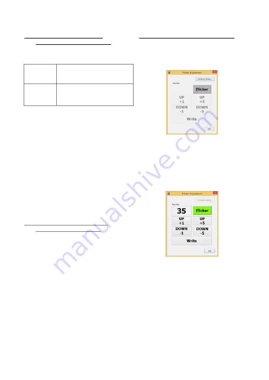
The flicker adjustment procedures by use of the flicker adjustment
tool are as follows:
1) Press [Connection Setting] button, and perform the
communication setting.
2) Press [Flicker] button, and the adjustment pattern is displayed
on the monitor and [Flicker] button turns to yellow-green color.
In addition, the current adjustment value is stored in Reg
Value (VCOM value) and [UP+1], [UP+5], [DOWN-1],
[DOWN-5], and [Write] buttons are enabled.
3) When [UP+1] or [UP+5] button is pressed, the Reg Value is
increased by 1 or 5 respectively (up to max. 127). When
[DOWN-1] or [DOWN-5] button is pressed, the Reg Value is
decreased by 1 or5 respectively (up to min. 0).
4) When [Write] button is pressed, the Reg Value is written as the
adjustment value.
5) When [Flicker] button is pressed again, the adjustment pattern
on the monitor disappears and [Flicker] button turns to gray
color. In addition, the Reg Value is deleted and [UP+1], [UP+5],
[DOWN-1], [DOWN-5], and [Write] buttons are disabled.
6) When [Exit] button is pressed, the tool is terminated. When the
tool is terminated with the adjustment pattern on the monitor
displayed, the adjustment pattern on the monitor is deleted.
Содержание PN-80TC3
Страница 150: ...PN L803C 80TC3 DISASSEMBLY AND ASSEMBLY 6 6 3 Remove the four screws M3x6 SW W Then remove LED Power Supply PWB ...
Страница 183: ...PN L803C 80TC3 TROUBLESHOOTING 7 10 FUSE POSITION MAIN PWB F2200 F2300 F2102 F2302 F2101 ...
Страница 184: ...PN L803C 80TC3 TROUBLESHOOTING 7 11 5V POWER SUPPLY PWB F2100 F2100 ...
Страница 191: ...PN L803C 80TC3 HARDWARE DESCRIPTIONS 8 7 3 BLOCK DIAGRAM Block diagram ...
Страница 202: ...PN L803C 80TC3 HARDWARE DESCRIPTIONS 8 18 5 PARTS LAYOUT Main PWB TOP ...
Страница 203: ...PN L803C 80TC3 HARDWARE DESCRIPTIONS 8 19 BOTTOM ...
Страница 204: ...PN L803C 80TC3 HARDWARE DESCRIPTIONS 8 20 LED Power Supply PWB TOP ...
Страница 205: ...PN L803C 80TC3 HARDWARE DESCRIPTIONS 8 21 BOTTOM ...
Страница 206: ...PN L803C 80TC3 HARDWARE DESCRIPTIONS 8 22 Key PWB TOP BOTTOM ...
Страница 208: ...PN L803C 80TC3 HARDWARE DESCRIPTIONS 8 24 5V Power Supply PWB connector Upper pin 5V Output Lower pin GND ...


