PN-L803C/80TC3 INSTALLATION, ADJUSTMENT, SETTING, OPERATION 2 - 3
1 – 3.CONNECTING PERIPHERAL EQUIPMENT
(Caution)
•
Be sure to turn off the main power switch and disconnect the plug from the power outlet before connecting/disconnecting cables. Also,
read the manual of the equipment to be connected.
•
Be careful not to confuse the input terminal with the output terminal when connecting cables. Accidentally reversing cables connected to
the input and output terminals may cause malfunctions and the other problems.
•
Do not use any cable that has a damaged or deformed terminal. Using such cables may cause malfunctions.
(MEMO)
-
When using a touch panel with a computer connected to the monitor, connect the USB cable to the computer. For details, see the Touch
Panel Settings Tool Operation Manual.
-
Images may not be displayed properly depending on the computer (video card) to be connected.
-
Use the automatic screen adjustment when a computer screen is displayed for the first time using D-SUB1 or D-SUB2, or when the
setting of the computer is changed.
The screen is adjusted automatically when SELF ADJUST in the MONITOR menu is set to ON.
-
If the audio output from the playback device is connected directly to speakers or other devices, the video on the monitor may appear
delayed from the audio portion.
Audio should be played through this monitor by connecting the playback device to the monitor’s audio input, and connecting the
monitor’s audio output to the speakers or other devices.
-
The audio input terminals used in each input mode are factory-set as follows.
Input mode
Audio input terminal
(Factory setting)
D-SUB1
Audio 1 input terminal
D-SUB2
Audio 2 input terminal
DisplayPort
DisplayPort input terminal
HDMI1
HDMI 1 input terminal
HDMI2
HDMI 2 input terminal
HDMI3
HDMI 3 input terminal
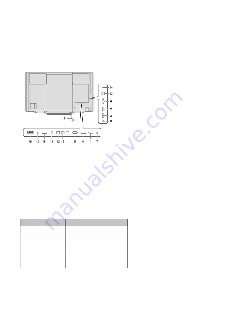
1. HDMI 1 input terminal
2. HDMI 2 input terminal
3. HDMI 3 input terminal
4. DisplayPort input terminal
5. D-sub 1 input terminal
6. D-sub 2 input terminal
7. Audio 1 input terminal
8. Audio 2 input terminal
9. DisplayPort output terminal
10. Audio output terminal
11. Touch pen adapter port
12. USB 1 (type B) port
13. USB 2 (type B) port
14.
RS-232C input terminal
15. LAN terminal
16. External speaker terminals
17. USB cable
Содержание PN-80TC3
Страница 150: ...PN L803C 80TC3 DISASSEMBLY AND ASSEMBLY 6 6 3 Remove the four screws M3x6 SW W Then remove LED Power Supply PWB ...
Страница 183: ...PN L803C 80TC3 TROUBLESHOOTING 7 10 FUSE POSITION MAIN PWB F2200 F2300 F2102 F2302 F2101 ...
Страница 184: ...PN L803C 80TC3 TROUBLESHOOTING 7 11 5V POWER SUPPLY PWB F2100 F2100 ...
Страница 191: ...PN L803C 80TC3 HARDWARE DESCRIPTIONS 8 7 3 BLOCK DIAGRAM Block diagram ...
Страница 202: ...PN L803C 80TC3 HARDWARE DESCRIPTIONS 8 18 5 PARTS LAYOUT Main PWB TOP ...
Страница 203: ...PN L803C 80TC3 HARDWARE DESCRIPTIONS 8 19 BOTTOM ...
Страница 204: ...PN L803C 80TC3 HARDWARE DESCRIPTIONS 8 20 LED Power Supply PWB TOP ...
Страница 205: ...PN L803C 80TC3 HARDWARE DESCRIPTIONS 8 21 BOTTOM ...
Страница 206: ...PN L803C 80TC3 HARDWARE DESCRIPTIONS 8 22 Key PWB TOP BOTTOM ...
Страница 208: ...PN L803C 80TC3 HARDWARE DESCRIPTIONS 8 24 5V Power Supply PWB connector Upper pin 5V Output Lower pin GND ...


