background image

3. SST-W100 Overview

Components (Savant Control System) 

Savant Host (Smart or Pro Host)
Wireless Network
Wired Network (Supplies voltage to power thermostat). 

Optional Components

SST-TEMP1-xx - Remote Indoor Temperature Sensor
SST-OTEMP1-xx - Remote Outdoor Temperature Sensor

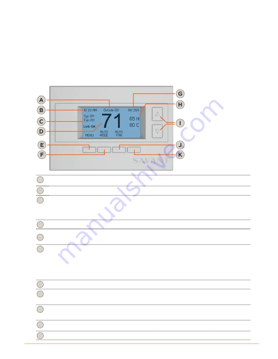
Front View

A

The Outside temperature displayed is retrieved from the remote sensor RS2 when configured as an outdoor 
sensor.

B

Displays local time. The time is using the 

Set Clock

 menu.

C

State of functions/relays in thermostat. See table in 

Main Thermostat Control Screen

 section for more 

information on the various states that can be displayed.
• Sys O

 - Relays in thermostat for HVAC system are in O

 state. HVAC is not running.

• Fan O

 - Fan relay is in O

 state. Fan is O

.

• Link OK - Connected to a local Wi-Fi network.

D

The temperature displayed is the local indoor temperature

E

Pressing the 

MENU

 button for the first time opens the 

SET CLOCK

 menu. Once the clock is set, pressing the 

MENU 

button will open the thermostat control screen. Pressing the 

MENU

 button from the thermostat control 

screen opens the 

Menu Selection

 screen.

F

The 

MODE

 button opens the following selections: 

OFF

 - The thermostat will not communicate with an HVAC system.

HEATING

 - Only calls for heat are sent to the HVAC system.

COOLING

 - Only calls for cooling are sent to the HVAC system.

AUTO

 - Calls for both heating and cooling are sent to the HVAC system.

EHEAT

 - The EHEAT only appears when the thermostat is set to control a heat pump system. EHEAT is 

typically used as a backup when failure to the compressor occurs. 

G

The relative humidity data displayed is retrieved from a humidity sensor internal to the SST-W100. 

H

The high and low setpoints are displayed. To increase or decrease the setpoints, press the up/down arrow 
button to the right of each setpoint. Once in the heating or cooling setpoint screen, the temperature can be 
raised or lowered.

I

The up/down arrow buttons are multipurpose buttons. In the screen shown, pressing the up or down arrow 
button will open the high and low setpoint windows. In other windows, the buttons are used to move up and 
down a list of items.

J

The 

FAN

 button opens the 

FAN MODE

 screen. From the 

FAN MODE

 screen the mode can be changed 

between 

On

 and 

Auto

. Select the correct mode for your HVAC system.

K

This button is used in the various menu screens for di

erent functions.

SST-W100 Wireless Thermostat Deployment Guide

Copyright © 2016 Savant Systems, LLC

009-0802-08  |  160225

5

of 50

Содержание SST-W100

Страница 1: ...hermostat SST W100 Deployment Guide Document Number 009 0802 08 Document Date Feb 2016 Document Supports da Vinci 7 0 45 Perseverance Way Hyannis MA 02601 Copyright 2016 Savant Systems LLC Savant com 508 683 2500 ...

Страница 2: ...ure 32 User and Maintenance Settings 35 Main Thermostat Control Screen 35 Set Clock 36 Filter Service 37 Maintenance Service 37 Screen Timeout 38 Set Temperature Scale 38 BackLite Display 38 Display Lock 39 Service Mode 39 Relay States 40 Restore Default Settings 40 Configuration Examples 41 Appendix A Menu Selection Screen Descriptions 43 Appendix B Installer Settings Screen Descriptions 45 Appen...

Страница 3: ... connected and controlling an HVAC system it can then be configured to a user s specifications Each menu on the LCD screen is described with example configurations Utilize this deployment guide to aid you in all aspects of installation and configuration of the SST W100 thermostat Before You Begin Read through this document in its entirety and ensure that the following required items are available ...

Страница 4: ...VAC See Wiring Diagrams 6 Configure the HVAC System Type See Set HVAC System Type 7 Configure Temperature Scale See Set Temperature Scale 8 Connect to local Wi Fi See Connect to local Wi Fi 9 Configure into RacePoint Blueprint See RacePoint Blueprint 10 Upload Configuration to Host See Upload Configuration 11 Connect to User Interface Savant App See Open User Interface Savant App 12 Connect to Use...

Страница 5: ...lowing selections OFF The thermostat will not communicate with an HVAC system HEATING Only calls for heat are sent to the HVAC system COOLING Only calls for cooling are sent to the HVAC system AUTO Calls for both heating and cooling are sent to the HVAC system EHEAT The EHEAT only appears when the thermostat is set to control a heat pump system EHEAT is typically used as a backup when failure to t...

Страница 6: ...l dehumidification fan when an air handler is used for dehumidification Terminal Block Right 24C Connect the common wire from the transformer on HVAC system to the 24C terminal When there is a separate heating and cooling system transformer the common wire from the cooling and heating system is wired here 24RH When there is a separate heating and cooling system the wire from the transformer on the...

Страница 7: ...iances that produce radiant heat or cooling If replacing an existing thermostat prior to removing switch off power to the heating and or cooling system During the removal process it is good practice to label each wire with the reference designator marked on the thermostat being removed Follow the instructions below to install the SST W100 thermostat 1 Separate the thermostat from its rear mounting ...

Страница 8: ... below Two Transformer Scenario Cut jumper JP1 to separate the 24RH and 24RC terminals JP1 is located on the bottom right side of the PCB Connect the hot side of the transformer powering the cooling system to the 24RC terminal Connect the hot side of the transformer powering the heating system to the 24RH terminal Connect the common wire from the transformer from the cooling system to the 24C term...

Страница 9: ... the thermostat should not be cut Standard One Stage Heat One Stage Cool Separate Fan Control Additional Information The SST W100 requires both the 24RC and 24C terminals connected to power the thermostat In this scenario a separate C ommon wire may need to be added The system employs only one transformer so JP1 inside the thermostat should not be cut In this system there is a separate fan that ca...

Страница 10: ...manually or through software on the thermostat Standard Two Stage Heat Two Stage Cool Separate Fan Control Separate Transformers Additional Information The system employs two separate transformers Connect one transformer to 24RC and 2nd transformer to 24RH The C ommon wire from each transformer is wired to the 24C terminal Jumper JP1 on circuit board must be cut or damage to thermostat can occur I...

Страница 11: ...ng valve to switch between heating and cooling Heat Pump Two Stage Heat Two Stage Cool Additional Information The SST W100 requires both the 24RC and 24C terminals connected to power the thermostat In this scenario a separate C ommon wire may need to be added The heat pump system employs only one transformer so JP1 inside the thermostat should not be cut HVAC systems employing a heat pump use a re...

Страница 12: ... ASCII Characters A Z a z 0 9 Firmware Prior to 2 13 00 Length 27 ASCII characters Spaces NOT allowed in Shared ID Passphrase ASCII Characters NOT allowed All other ASCII characters above are acceptable Restore Wi Fi to Defaults The Wi Fi radio can be restored to its default settings To do this follow the steps below 1 From the main window setup screen press the MENU button to open the Menu Select...

Страница 13: ...s client Note Each router s WPS setup is different Refer to the router s instructions on how setup and enable the WPS standard 3 Press the MENU button to open the Menu Selection window 4 Scroll to and Select the WiFi Setup option This opens the WiFi Setup window 5 Scroll to and Select the WPS Connect option 6 A WPS Connect Status window will open and display the connection status 7 After a few seco...

Страница 14: ... port 2000 Accept the default unless a different port is required To modify the port number Scroll to the Port option and press the Select button The Edit Port window will open Using the up down arrows and left right arrows edit the Port number Select Done when complete 4 Scroll to and Select the SSID option This will open the WiFi Networks window 5 Scroll down the list to the local network Press t...

Страница 15: ... the IP Address of the DNS server Select Done when complete Port The default is port 2000 Accept the default unless a different port is required To modify the port number Scroll to the Port option and press the Select button The Edit Port window will open Using the up down arrows and left right arrows edit the port number Select Done when complete Chan The default is set to Auto Accept the default ...

Страница 16: ... local network 7 Select Done when complete The SSID entered will automatically populate itself into the SSID field of the WiFi Setup screen 8 Scroll to and Select the Key field This will open the Enter Passphrase window 9 Using the up down arrows and left right arrows enter the Shared Key Passphrase of the local network 10 Select Done when complete 11 The SST W100 will now connect to the network W...

Страница 17: ... 4 Verify there is communications between the thermostat and either the router or Savant Control system 5 Select Done when complete Display the WiFi Network Status To display information such as the IP Address of the thermostat and SSID of the network the WiFi Network Status screen can be used Follow the steps below to view the WiFi Network Status screen 1 Press the MENU button to open the Menu Se...

Страница 18: ... System Type in your system If however the System Type is a heat pump press the Setup button to open the Mechanical Settings screen 4 From the Mechanical Settings screen configure the HVAC System Type and Fan Type fields Use the arrow buttons to scroll and the buttons to modify the settings 5 Press Done twice when HVAC System Type and Fan Type have been configured This will return you to the Menu ...

Страница 19: ...at there is an existing Savant Control system configured and the Smart Host or Pro Host and iOS device is already part of an existing configuration 1 Open the existing RacePoint Blueprint configuration 2 From menu bar select RacePoint Blueprint Preferences to open the RacePoint Blueprint Preferences screen 3 Select the Update UI Defaults tab Verify the Enable HVAC screen population option is check...

Страница 20: ... thermostat is placed in a User Zone the thermostat service that gets created can only be displayed in that zone room of the Savant App TrueControl II user interface Shared Equipment When the thermostat is placed in a Shared Equipment zone the thermostat service that gets created can be displayed in any zone room of the Savant App TrueControl II user interface This is configurable by checking or u...

Страница 21: ...he Network Device 4 From the Blueprint tool bar click the Show Inspector icon This will open an Inspecting Data window 5 Double click the Host address field and enter the IP Address of the thermostat If you don t know the IP Address it can be obtained following the Display WiFi Network Status section 6 If required modify the port number from its default of 2000 Repeat this process for all thermost...

Страница 22: ...t Tools Settings HVAC This will open the HVAC data table shown below 2 How the data table is configured affects what is populated in the User Interfaces of the Savant App and TrueControl II App Use the table below to configure each column as required Column Description Enabled Check the box to enable the row and generate an HVAC screen on the User Interface Savant App TrueControl Unchecked boxes wi...

Страница 23: ...tes the Heat and Cool columns with a check as well The Auto column does not affect TrueControl or TrueControl II For more information on configuring the data tables for the SST W100 refer to the HVAC Data Table Overview Application Note and Data Table Overview Application Note on the Savant Community Map the Thermostat Data to a zone room The Savant App Zone Map button located on the HVAC data tabl...

Страница 24: ...rvices Preferences Table that appears 3 Select Done 4 Select Update All UI Screens Sync with Services drop down menu from the Services for Thermostat dialog window that appears 5 Select the Sync button to the Sync with Services warning that appears 6 Verify the State Icon on the RacePoint Blueprint tool bar is now illuminated green SST W100 Wireless Thermostat Deployment Guide Copyright 2016 Savan...

Страница 25: ...elect to highlight the ThermostatAddress option and then select ThermostatCurrentRemoteTemperature from the drop down menu See image below 6 In the Unique Identifier window enter the number 1 into the Value column See image below 7 Select Done when complete 8 The State Name selected from the Status Variable menu will now appear in the Outdoor Temperature State drop down window 9 Select Done when c...

Страница 26: ...6 The screen is blue indicating a cooling call is in progress The heating and cooling setpoints are the blue and orange dots to the right of the screen Tapping on either the cooling or heating setpoint dot will open the Heat Setpoint screen The cooling setpoint blue dot is below the real time temperature displayed which is why the call for cooling occurred The screen above displays the following D...

Страница 27: ...ove displays the following The current indoor and outdoor temperatures The current humidity level The thermostat is calling for stage 1 cooling Fan is currently running The Heat and Cool setpoints The HVAC Mode selected The Fan Mode selected All settings are modified by tapping each of the settings The Climate screen above displays information from the previous screen but in this screen The thermo...

Страница 28: ...n the Menu Selection screen 2 Scroll down and Select the Humidity Settings option 3 Scroll down to the RH Setpoint option Increase or decrease the RH Setpoint by pressing the buttons to the desired humidity setpoint Humidity Monitoring Icon To eliminate the humidity from being displayed on the front LCD display main configuration screen do the following 1 From the main window setup screen press th...

Страница 29: ...relay to control an external dehumidifier For the auxiliary relay to activate the HVAC mode must be set to either Cool or Auto and the last call needed to be for cool A1 or A2 Relay Net Instructs the auxiliary relay to be controlled by the Savant Control system and the relays activate depending on certain triggers and workflows set in the Savant software A1 or A2 Relay Vent Instructs the auxiliary...

Страница 30: ...nitiated because the temperature rises above the Cooling Setpoint The HCL function extends the cool cycle and allows the temperature to continue to drop below the Cooling Setpoint if the RH Setpoint RH SP Delta is not reached If the temp drops below the Cooling Setpoint by more than the Cooling Setpoint RH Temp Delta the cooling cycle is terminated RH Temp Delta Range 1 F 5 F Example Cooling SetPo...

Страница 31: ...int RH SP Delta has not been reached The function of the RH Off Delta is to terminate the cool cycle when the humidity reaches the RH Setpoint RH Off Delta Differential Percentage Range 0 to 10 Example Cooling SetPoint 80 F RH Setpoint 45 RH SP Delta 4 RH Off Delta 2 RH Temp Delta 3 F A cooling cycle is initiated because the temperature rises above the Cooling Setpoint of 80 F The cooling cycle lowers...

Страница 32: ...bottom right of the LCD screen 4 Modify the opposite setpoint by pressing the up down arrow buttons to the desired setpoint 5 Select Done when complete 6 The cooling and heating setpoint will now be displayed on the main thermostat control screen Refer to image below Maximum Minimum Temperature Setpoints The maximum and minimum temperature setpoints configure the maximum and minimum values the hea...

Страница 33: ...es The indoor temperature is retrieved from the internal sensor and displayed as the main temperature The outdoor temperature is retrieved from RS2 and displayed as Outside temp just above the main temperature Internal RS1 RS2 outdoor No Yes No Yes When RS1 is connected this disables the internal sensor The temperature from RS1 is displayed as the main temperature The outdoor temperature is retrie...

Страница 34: ...digital thermometer next to the Internal temperature sensor and allow it to acclimate to the temperature in the room Make note of this temperature 2 Press the MENU button to open the Menu Selection screen 3 Scroll to and Select the User Settings option to open the User Settings screen 4 Scroll to and Select the Sensor Calibration option to open the Sensor Calibration screen 5 Scroll to the Interna...

Страница 35: ...Heat or Cool This button is located on the bottom right of the LCD screen Modify the opposite setpoint by pressing the up down arrow buttons to the desired setpoint For more information on setpoints refer to the Temperature Setpoints section HOLD Since all scheduling is configured through either the Savant App or TrueControl App the HOLD functionality is not used and hidden If the HOLD functionali...

Страница 36: ...ll flash indicating it needs to be set Press the MENU button 2 After pressing the MENU button the Set Clock menu shown below will appear Use the buttons to set the Time and Date Pressing the up down arrow buttons will increase or decrease the characters on the screen that are highlighted Pressing the left right arrow buttons move the cursor to the left or right Once cursor gets to the end of each ...

Страница 37: ...ress the MENU button to open the Menu Selection screen 2 Scroll to and Select the User Settings option 3 Scroll to and Select the Maint Service option Heat Runtime Number of hours the heating system has run since the last time Service Interval was reset Cool Runtime Number of hours the cooling system has run since the last time Service Interval was reset 4 Using the buttons set the Service Interva...

Страница 38: ...option 3 Scroll to and Select the F C Settings option 4 Using the buttons set to either F fahrenheit or C celsius 5 Select Done when complete BackLite Display The lighting and contrast levels on the LCD display can be modified See information below 1 Press the MENU button to open the Menu Selection screen 2 Scroll to and Select the User Settings option 3 Scroll to and Select the Backlite Display o...

Страница 39: ... 3 seconds Refer to the Humidity Monitoring Icon for instructions 3 From the Installer Settings screen scroll to the Display Lock option 4 Using the buttons select N to unlock the buttons 5 Select Done when complete Service Mode The SST W100 can be set to run tests to the system To achieve this select Test Mode under Service Mode WARNING In Test Mode all system safety delays are shortened Do not o...

Страница 40: ...1 O B Fan Y1 Y2 A1 and A2 are displayed in Relay Status screen 4 Select Done when complete Restore Default Settings 1 Press the MENU button to open the Menu Selection screen 2 Press and hold the two middle buttons After about three seconds the Installer Settings screen will open 3 From the Installer Settings window scroll down to the Restore Defaults option 4 Press the Select button 5 In the next ...

Страница 41: ...ns set the Fan Type to either Gas or Elec TIP Fan Type Electric Selecting Elec will activate the fan relay for heating and or cooling calls Fan Type Gas Selecting Gas will activate relay for cooling calls only 10 Using the buttons set the 2nd Stage Heat and or 2nd Stage Cool to Y to enable each If the HVAC system only supports heating or cooling set the stages as required Below are the settings fo...

Страница 42: ...eating mode and requires a change over to reverse flow to cooling mode C O Type w Heat For a reversing valve that works normally energized in the cooling mode and requires a change over to reverse flow to heating mode Typically the B terminal 10 Using the buttons set the 2nd Stage Heat to Y to enable If the HVAC system only supports heating or cooling set the stages as required Below are the setti...

Страница 43: ...nsor The temperature displayed in the Sensor Calibration screen is what will be displayed in the main thermostat control screen See Calibrate Sensors Backlite Display The Backlighting and contrast levels on the LCD display are modified in the BackLite Display screen See BackLite Display RH Mode Enables and disables the Humidity Control Logic HCL See Configure HCL RH Setpoint Used to set the Relati...

Страница 44: ...r the IP Address If there is no DNS the IP Address given will match the IP Address given to the local router Port The Default port number is 2000 If connecting to the router through a different port the port number can be entered manually Chan The default is set to Auto The thermostat will scan all the channels looking for the correct channel to join the network Alternatively if the channel of the ...

Страница 45: ...en test mode is enabled all system delays are shortened On systems utilizing a heat pump do not operate the system compressor in Test Mode Disconnect the Y1 and Y2 outputs if applying Test Mode on a live system N No Test Mode is disabled Normal system delays Network Settings Network Addr Network Address should be set to 1 This is the address entered into Blueprint for all thermostats added to the ...

Страница 46: ...urge Keeps the fan running after either a heating or cooling cycle has ended Using the buttons the duration of the purge can be set between 30 and 120 seconds with the default set to 0 seconds Off H Delta Stg1 ON Configures the number of degrees below the heating setpoint before stage 1 heating is engaged Range 1 F to 6 F Default 1 F H Delta Stg1 OFF Applicable after heat stage 1 has been running H...

Страница 47: ...tion for more information RS2 location The location of the remote sensor RS2 is configured here RS2 can be configured as an indoor or outdoor sensor When configured as an indoor sensor the temperature displayed is an average between RS2 and either RS1 or the internal sensor When configured as an outdoor sensor the outside temperature is displayed on the LCD See the Temperature Sensors section for ...

Страница 48: ...in the router By using this method static IP Addresses for all devices can be managed from a single UI avoiding the need to access devices individually Setting DHCP reservation varies from router to router Refer to the documentation for the router to configure DHCP reservation Network Changes Savant recommends performing the following steps to refresh the IP connection after connecting to a new ne...

Страница 49: ...ms LLC All rights reserved Savant Savant App Savant Host Now You Can RacePoint Blueprint Single App Home TrueCommand TrueControl and the Savant logo are trademarks of Savant Systems LLC AirPlay Apple AirPort Express AirPort Extreme Apple TV Apple Remote Desktop FireWire iMac iTunes iPad iPad mini iPad Air iPhone MacBook Mac and OS X are trademarks or trade names of Apple Inc iOS is a trademark of ...

Страница 50: ...ation If this equipment does cause harmful interference to radio or television reception which can be determined by turning the equipment off and on the user is encouraged to try correct the interference by one or more of the following measures Reorient or relocate the receiving circuit different from that to which receiver is connected Increase the separation between the equipment and the receiver ...

Отзывы: